 Simon Trendel
So now we are at a state, where we want object pose estimation from our sensor data. This is kinda problematic, because the lighthouses are not perfect. They are optical systems with certain manufacturing tolerances. There is a reddit discussion concerning the factory calibration values and their meaning. This videos is explaining the values to some extend, while this video describes some of the strategies to cope with those values.
First of, we had to implement an ootx decoder in fpga, that continuosly decodes the frames from both lighthouses. That was fun and the decoded values are sent via a ROS message to our host.
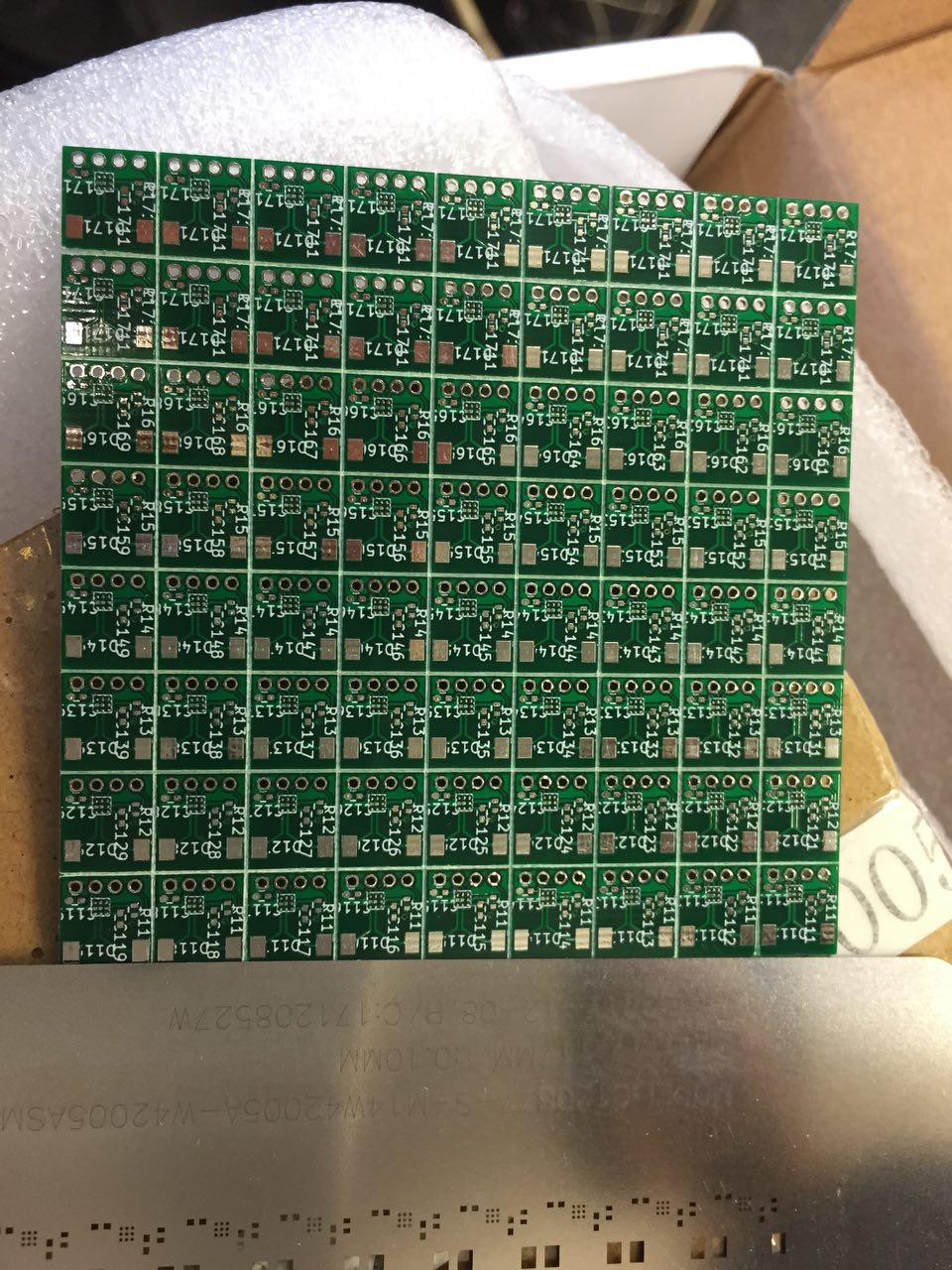
So far, we have been using exclusively our own custom sensors, and are pretty confident that those produce comparable signals to the original HTC ones. But you never know until you try. Also Valve has announced their second generation of the lighthouses which will do something called sync-on-beam. We are not sure what exactly that is, but we have the strong believe that this might be related to a modulation of the MHz infrared light to convey information while the beam sweeps each sensor. This would allow for an almost arbitray amount of lighthouses. Our sensors are not able to decode such a signal. Triads second generation of the sensor amplifier TS4231 are. So we ordered those and we had the pcbs manufactured.
Over the holidays our pick-and-place machine is resting. Which is boring of course, but we decided to push simulation further and extend the overall system to be able to track multiple objects. We are using autodesks fusion 360 for CAD design, because it is free for students and it has an extensive python API. The API allows you to write your own plugins for fusion. We are working on tendon robots, so those plugins come in very handy when defining attachment point of the tendons for example.
So the first thing we did, was to implement a plugin for the sensor positions on our robots. When you run the plugin, it lets you choose for which link you want to define the sensor positions and then you simply click on your model where you want those sensors. I might upload a video later. You can find the plugin here: https://github.com/Roboy/DarkRoomGenerator
Another plugin we have written is a sdf exporter. It lets you export your robot from fusion to sdf. Then you can load that model into the gazebo simulator. This plugin can also export the lighthouse sensor positions. These can then be loaded by our system and used for pose estimation. You can find the plugin here: https://github.com/Roboy/SDFusion
In the following video you can see a simplified model of the upper body of roboy2.0. The green spheres are the simulated sensor positions. Currently our pose estimator tries to match the relative sensor positions (as exported from fusion) to the triangulated 3D positions. The resulting pose is quite ok, although fails for some orientations. This could be because of ambiguity, but needs further investigation ( EDIT: the pose estimator works fine, it was just my crappy pc that couldn't keep up with the computation. This caused the simulated sensor values to be updated asyncronously)
Because the visual tracking alone is not good enough, we extended our system to also include IMU data. This is done via the ROS robot_localization packages' extended kalman filter. So now, everything is prepared for the real data. Once the new sensors are assembled we will try to figure out, how to use those factory calibration values to get good lighthouse angles.
Discussions
Become a Hackaday.io Member
Create an account to leave a comment. Already have an account? Log In.