 ogdento
This is an easy project to make if you're looking for a simple serial display for a project or even just for debugging. I used TinyCAD to draw the schematic, VeeCAD to do the vero/strip board layout, and OpenSCAD to do the case. All of the source files are attached to the project.
HARDWARE
I used a PIC16F688 because that's what I had lying around. It's a 14-pin part with no hardware PWM but I used a simple interrupt routine to generate 30 different pulse widths, 0 being nothing and 30 being full on. It's running at 4mhz on the internal oscillator.
The board is powered by a 3.3 volt regulator because the LCD can not handle 5 volts. The LCD is reportedly supposed to run at 2.8 volts but mine has been working fine at 3.3. I meant to put a reverse voltage protection diode at the regulator input but I never got around to it.
I added an ICSP (in circuit serial programming) header so that I could modify the firmware without taking the whole darned thing apart.
My 1100 lcd came with a built-in speaker and I drilled a hole through the case to access the +/- terminals on the speaker but I have not yet hooked it up. I did test it though and it makes a decently loud low frequency beep.
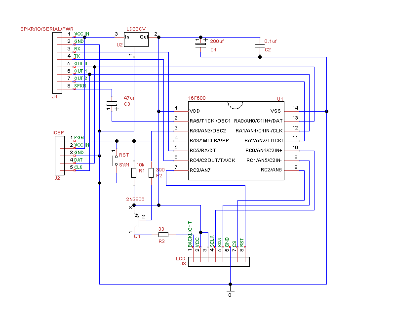
Here is the schematic:
SOFTWARE
When Peter Andersen passed away his code was left to be maintained by Paul Badger and Brian Riley and released to the public under the MIT license. I took the LCD117E version of the code and changed it for compilation with Microchip's Mplab v8.73 IDE and the Hitech C compiler - I haven't gone to Mplab-x yet, but it shouldn't be that hard to make it work there.
The LCD117E code was built to work with a Hitachi compatible character display - which the Nokia 1100 is not - so some of the original features do not work, such as setting the cursor type. I also modified the code to work with a Nokia 1100 library I got years ago from Spiralbrain's blog. His site is down and his blog is no longer active, but the archived version of his site says his code may be used for non-commercial purposes.
https://web.archive.org/web/20120102020033/http://www.sunbizhosting.com/~spiral/1100/
The baud is set to 19200 but it can certainly be changed in code. I haven't done it yet but I plan to add another command to set the baud rate. Peter Anderson didn't originally allow for run-time baud rate changes because he didn't want to have a situation where the baud rate would be unknown, but I show it on start-up.
The code is still a little rough, and has a lot of stuff commented out but it is working well enough for me to use the device. In the future I plan to add some graphics capabilities - maybe dot, line, and shape commands - but I haven't needed them yet.
I finally added the code to github:
https://github.com/ogdento/lcd117e_nokia
ENCLOSURE
The case didn't come out great but it works... the 4 legs of the case were too long because my math skills are apparently poor, but this was only the 2nd thing I ever designed in OpenSCAD. My screw posts are also about 1 mm too close together in both directions. Everything was measured with a set of standard vernier calipers (0.001") and then I scaled the whole thing in Cura because it wanted to print in mm. I probably should have used mm all along. I also think my printer's z-step is off.
It could use some improvements such as fixing the leg height, adding more material where the display is screwed down, and adding a slot for the ICSP header and maybe a printed button cap for the reset switch.
USAGE
Using this thing is pretty easy. On the left side of the case is an 8-pin header, and below that is a 5-pin ICSP header. The 8-pin header is where the magic happens:
- Vcc In - input voltage to the 3.3 volt regulator
- Gnd - ground
- RX - character input (RC5 on pic16f688)
- TX - character output (not currently used, reserved for future)
- Out 0 - general purpose output (RA0 on pic16f688)
- Out 1 - general purpose output (RA1 on pic16f688)
- Out 2 - general purpose output (RA2 on pic16f688)
- Spkr - beep output to small speaker
Connect power (there's an onboard...
Read more »
 tinu
tinu
 Tom Dowad
 Ken Yap
 Dan Julio