 esben rossel
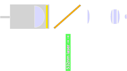
The schematic for the Raman setup is:
In real life it looks like this: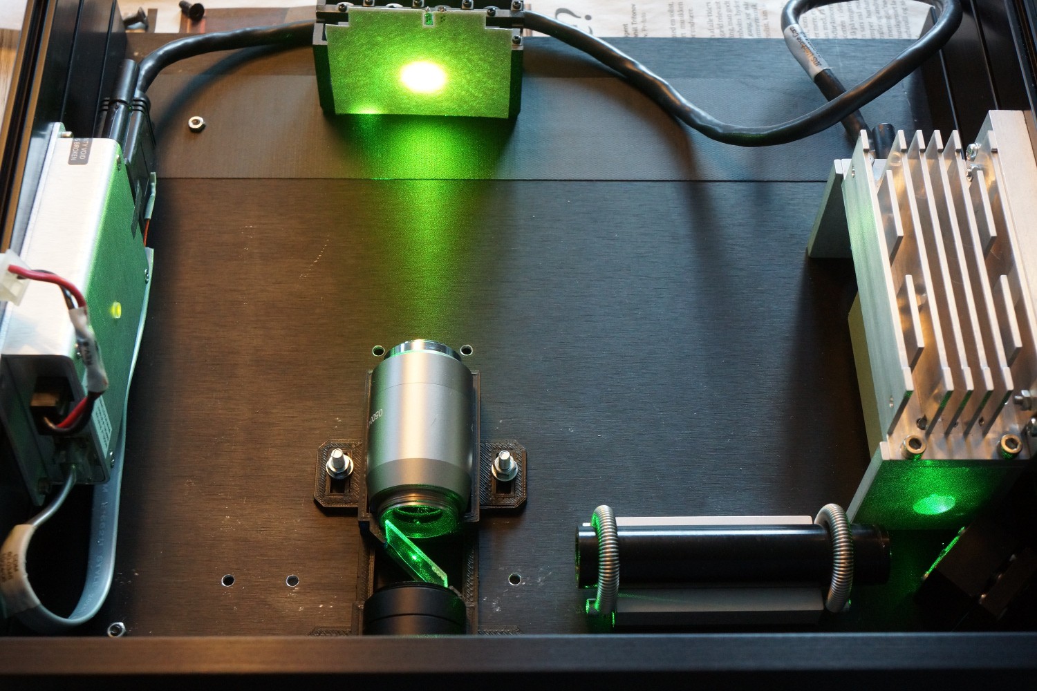
The laser is a 10 mW JDSU µgreen 532 nm laser. It operates in single longitudinal mode (SLM). The laser has no beam shaping optics, and the beam is somewhat divergent. This is "fixed" with a beam-expander (the long black tube). I'm not sure this is essential. Everything was carefully aligned one component at a time.
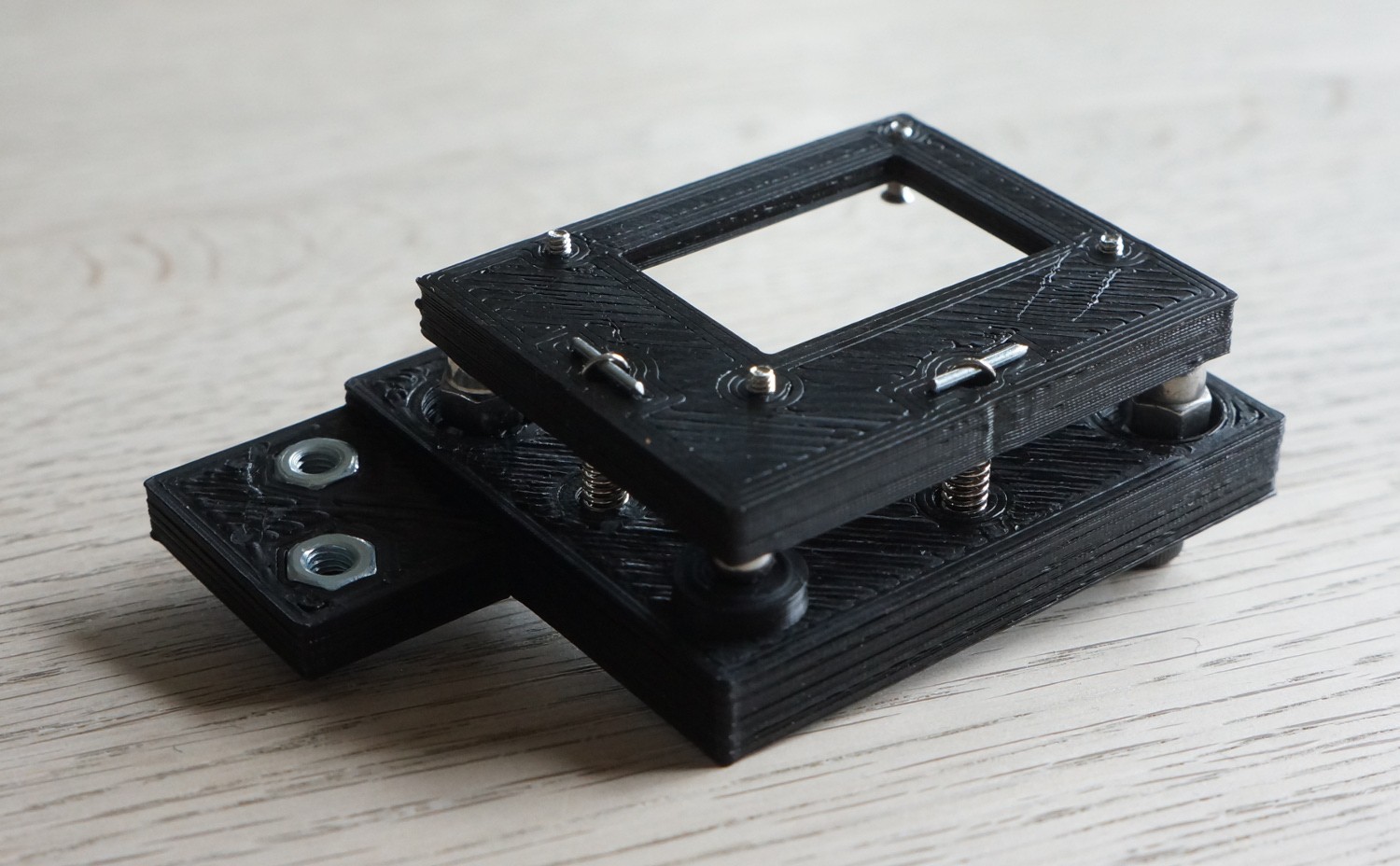
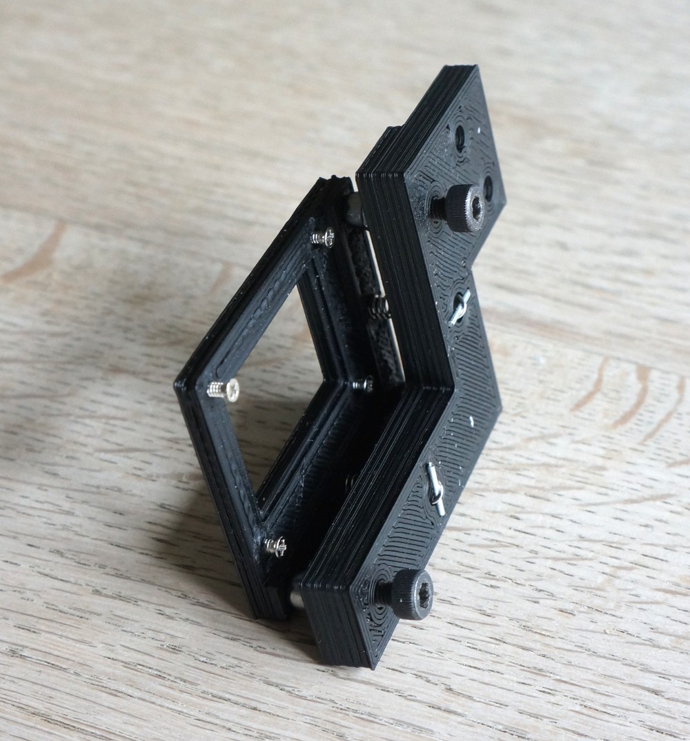
I would recommend a kinematic mount for the dichroic mirror - I didn't have that at the time of writing, I had a hair-drier (to heat, soften and adjust the 3D-printed holder). It could look something like this:
The "target" is an electroluminescent backlight that I use because it fluoresces in the 532nm laser light.
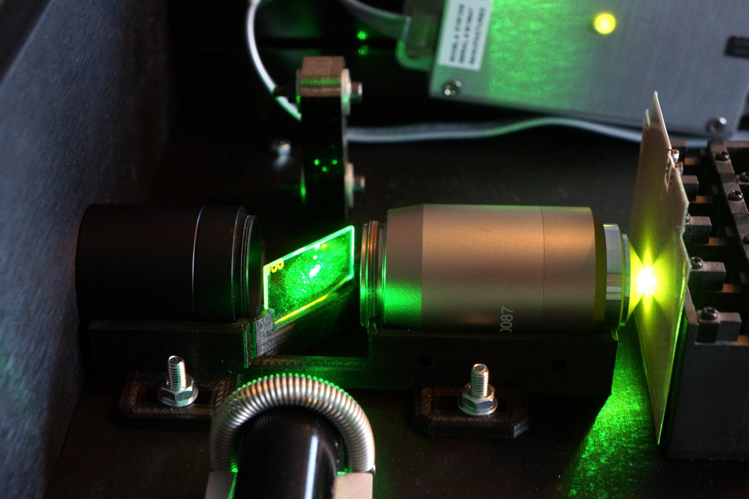
Here the EL-backlight is placed in the focal point of the microscope objective. In the background you see a razor blade beam dump.
Everything, literally, needs to be carefully aligned. Below you see the difference in light output before and after the last alignment of the dichroic mirror (oh and this time it's not the EL-backlight fluorescence we're looking at, but the fluorescence of a solution of tetraphenylporphyrin):

Discussions
Become a Hackaday.io Member
Create an account to leave a comment. Already have an account? Log In.