 Tron9000
<thumbs note book>
OK, so I've start this project before submitting it. Best bring it up to date...
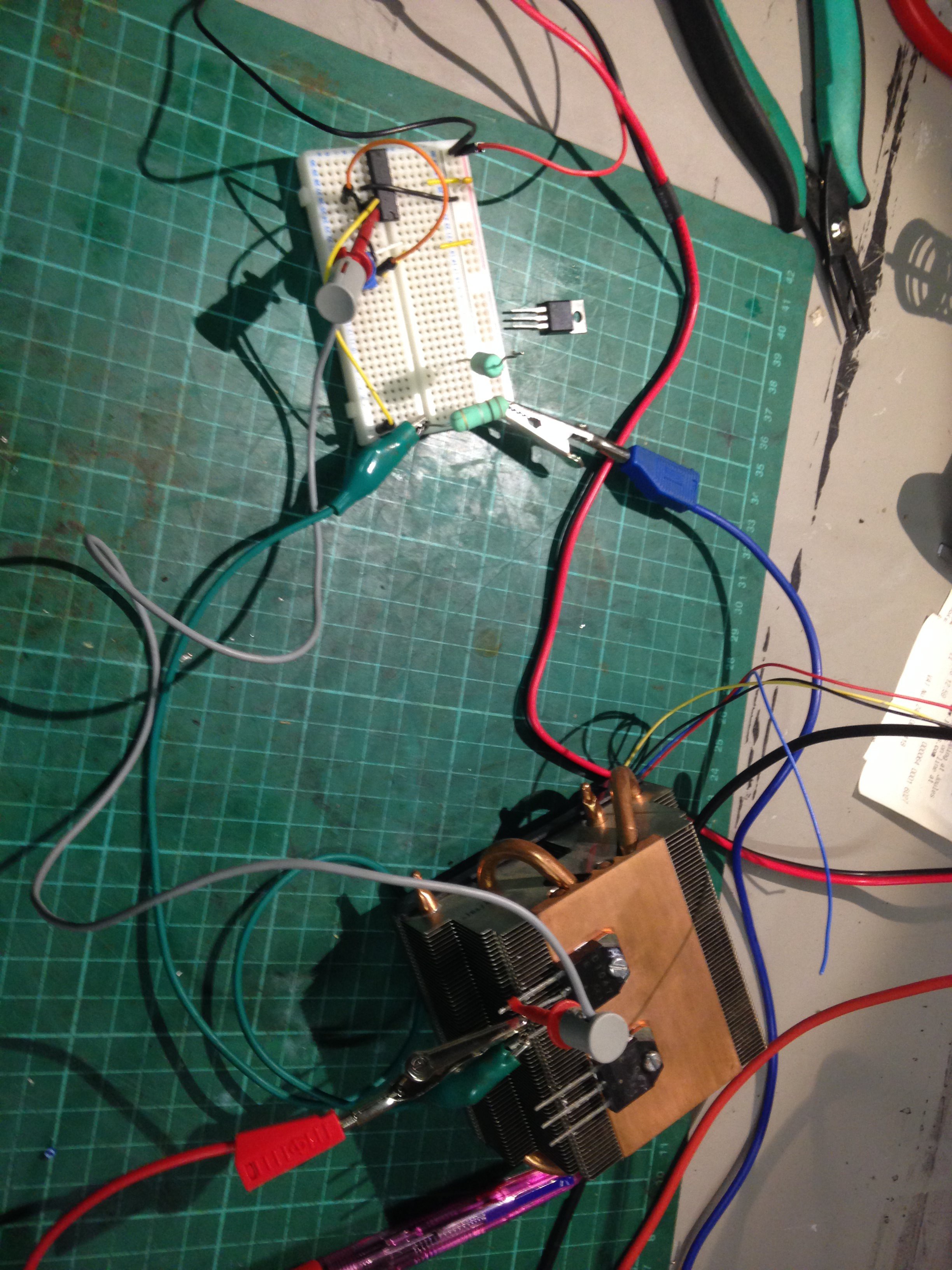
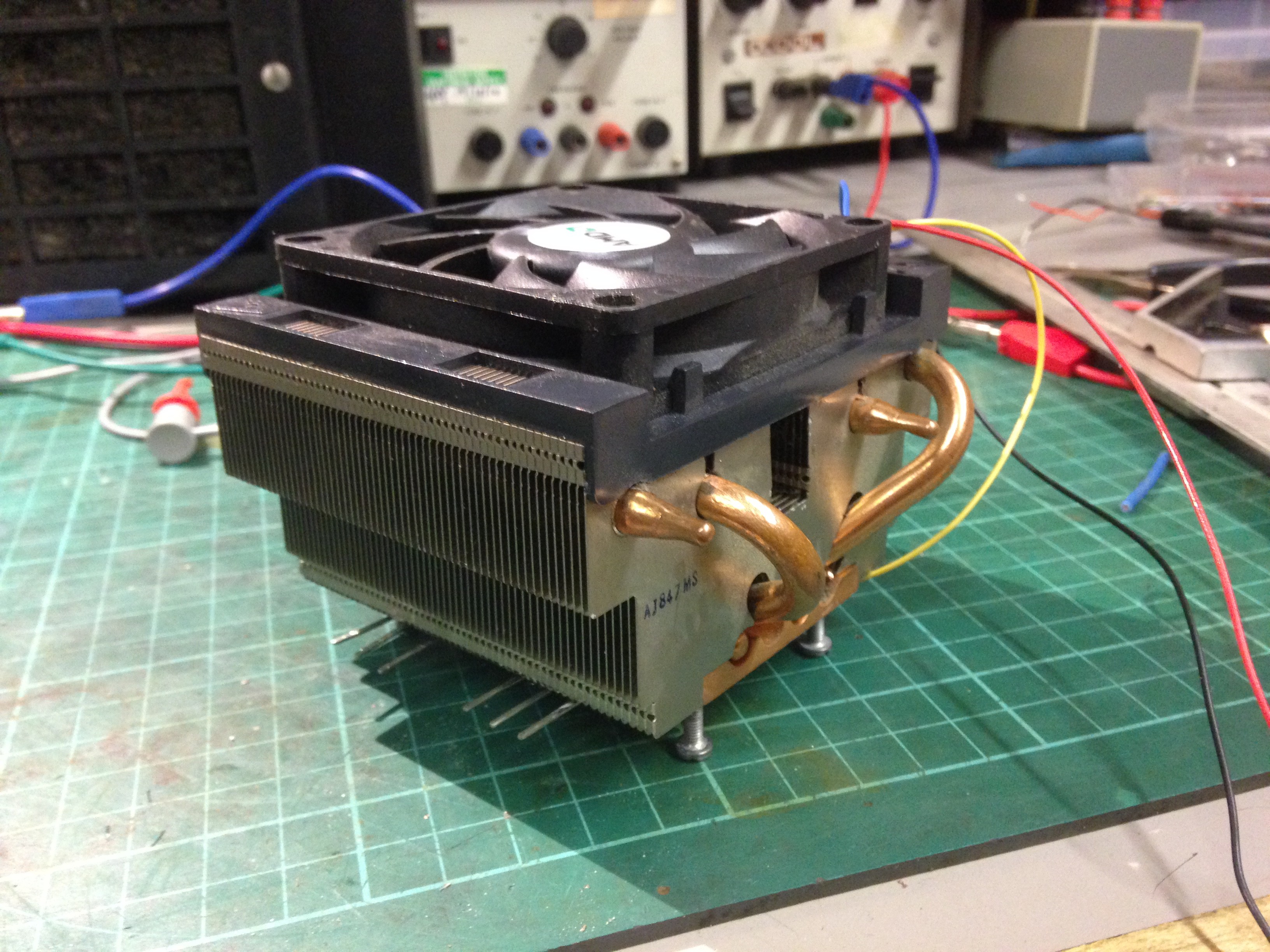
Firstly I got myself a beefy heatsink (one that was supplied with an AMD Phenom2 I bought ages ago) that would fit into the enclosure and drilled and tapped 2 holes for 2x D1047 transistors (like 2n3055) and mounted them onto it with some thermal paste.
Why accomodate 2? well just in case I wanted more amps!
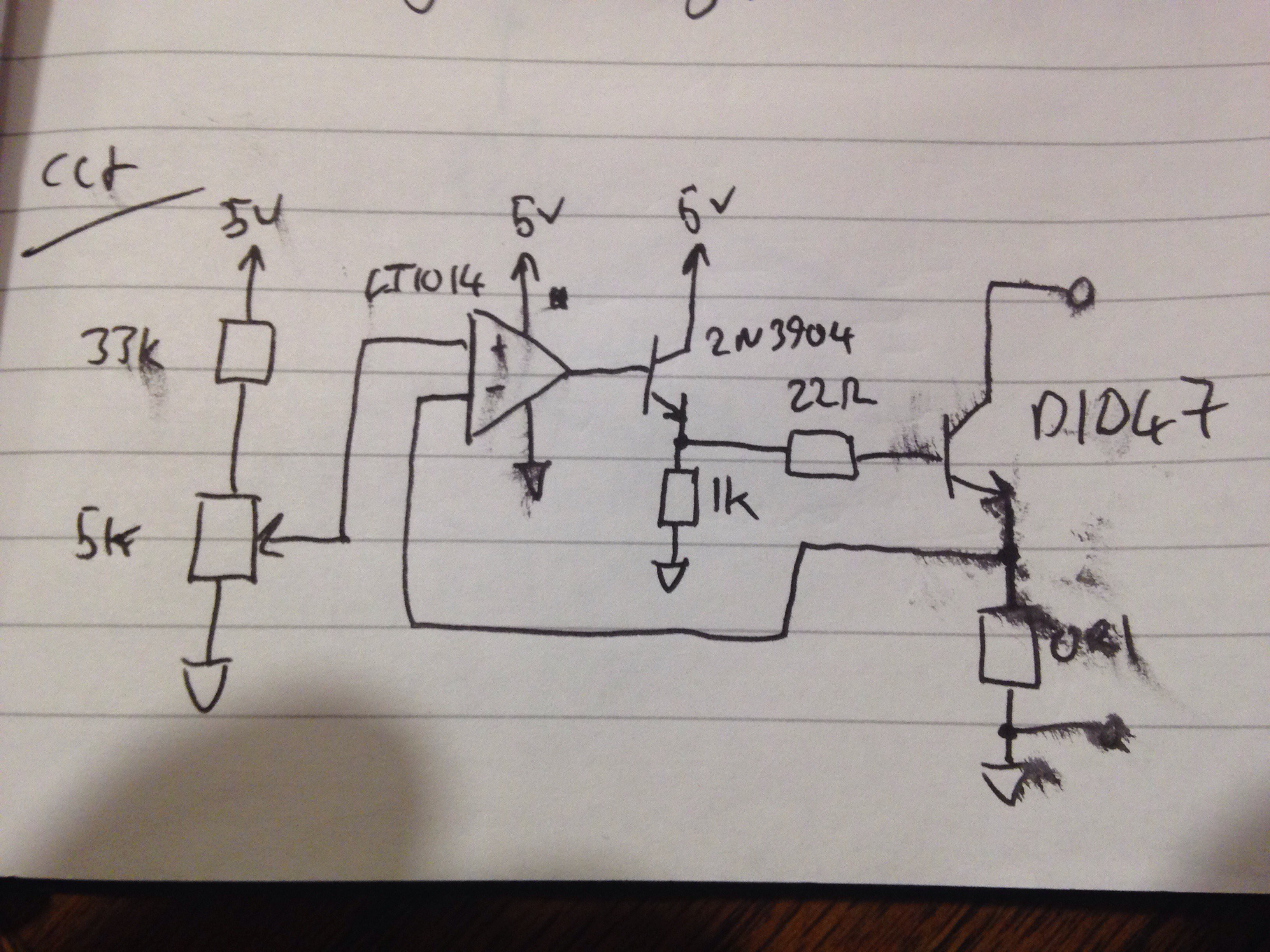
I then built up the circuit I intended to use:
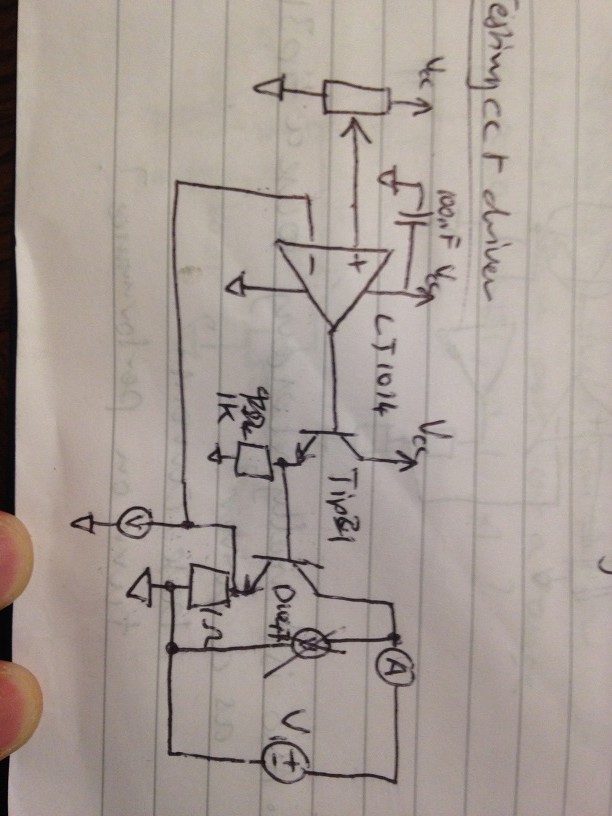
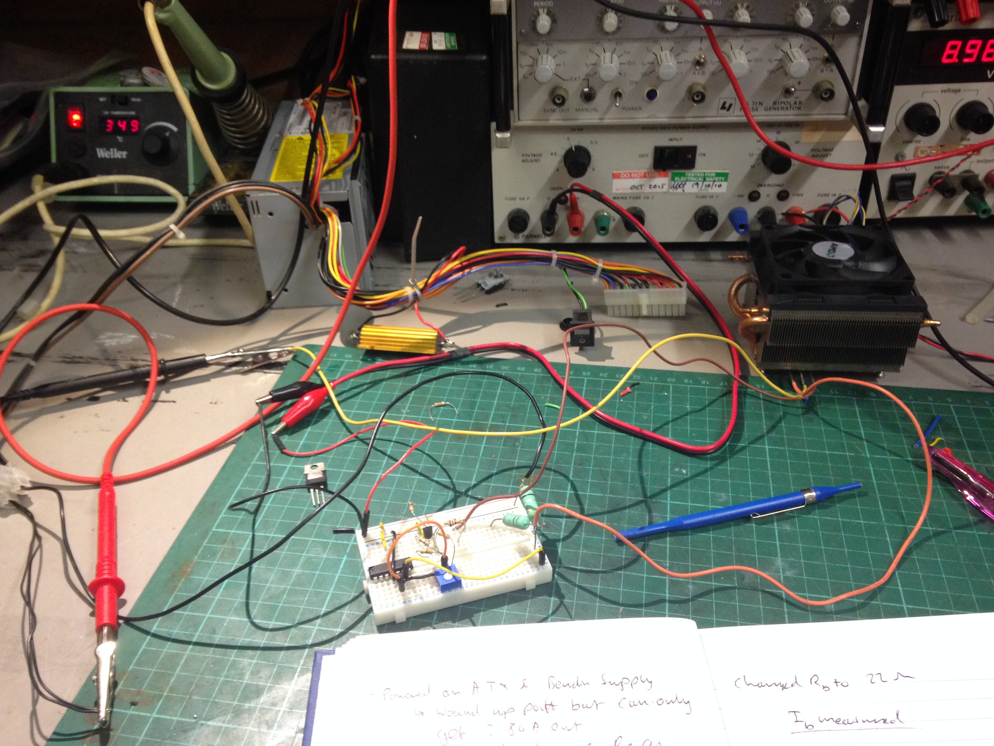
Using another bench supply as a load and running my circuit off a separate 5V supply, it worked as I expected. However, 2 things were an issue:
- Using a 1R resistor: it was getting hot
- the bench supply I was using for load could only do 2.2A - I needed a beefier supply - I managed to dump 60W though!
- The heatsink had a fan on it and I'd like to use it! The pass transistor was getting hot enough to not bear touch it (which is roughly 60 degC or so)
In short I wanted MORE!
SO i swapped the 1R out for a 0R1 resistor.This made things very sensitive! For every 100mV on pot meant 1A through the Pass transistor. However the resistor was not getting hot now cos P=IV=1*0.1=100mW rather than the 1W as before.
I then started on modifying the wiring on the fan on the heatsink and ran it off the 12V line off the same power supply I was running the electronics off (for those interested: its an old farnell TOPS2 power supply).
However the heatsink unit was a bit unsteady on the bench when placed fan side up, So I decided to drill and tap 4 more holes in each corner of the heatsink so I could stand it on the bench...
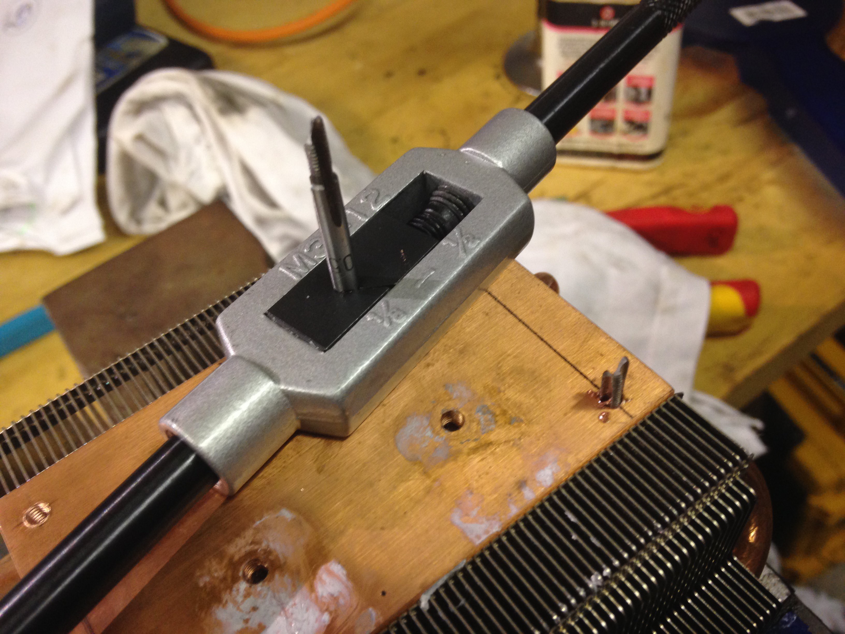
![]()
...well that's buggered it!
I was able to remove the broken tap and there was enough thread to screw in an M3 screw and was able to place it on the bench with out wobbling about.
I then butchered an old ATX power supply that could deliver 17A on its 12V rail. Tis was going to test the amount of current I could pull.
With this setup I managed to pull a little over 5A @ 12V = 60W again. with a slight modification to the circuit I was able to pull nearly 10A for about 5 seconds, but got scared and didn't want to break things just yet. The Heatsink was nice and cool @ 60W now.
Now the keen eye'd amongst you will see that the buffer transistor on the breadboard has changed from to-220 to to-92. Whilst modifying the circuit I found the TIP31 was getting warm and whilst removing it I thought that this part of the circuit was a bit poorly designed. So I changed it for a 2n3904 and stuck a 22R resistor as a base resistor to the pass transistor. I also put a 33k resistor in series with the setpoint pot so I got a sensible amount of rotation on the pot.
So Whats next?
- I want to see the transient response of the current on this circuit and if needs be calculate a suitable feedback network to avoid any overshoot.
- select components and build a reference circuit
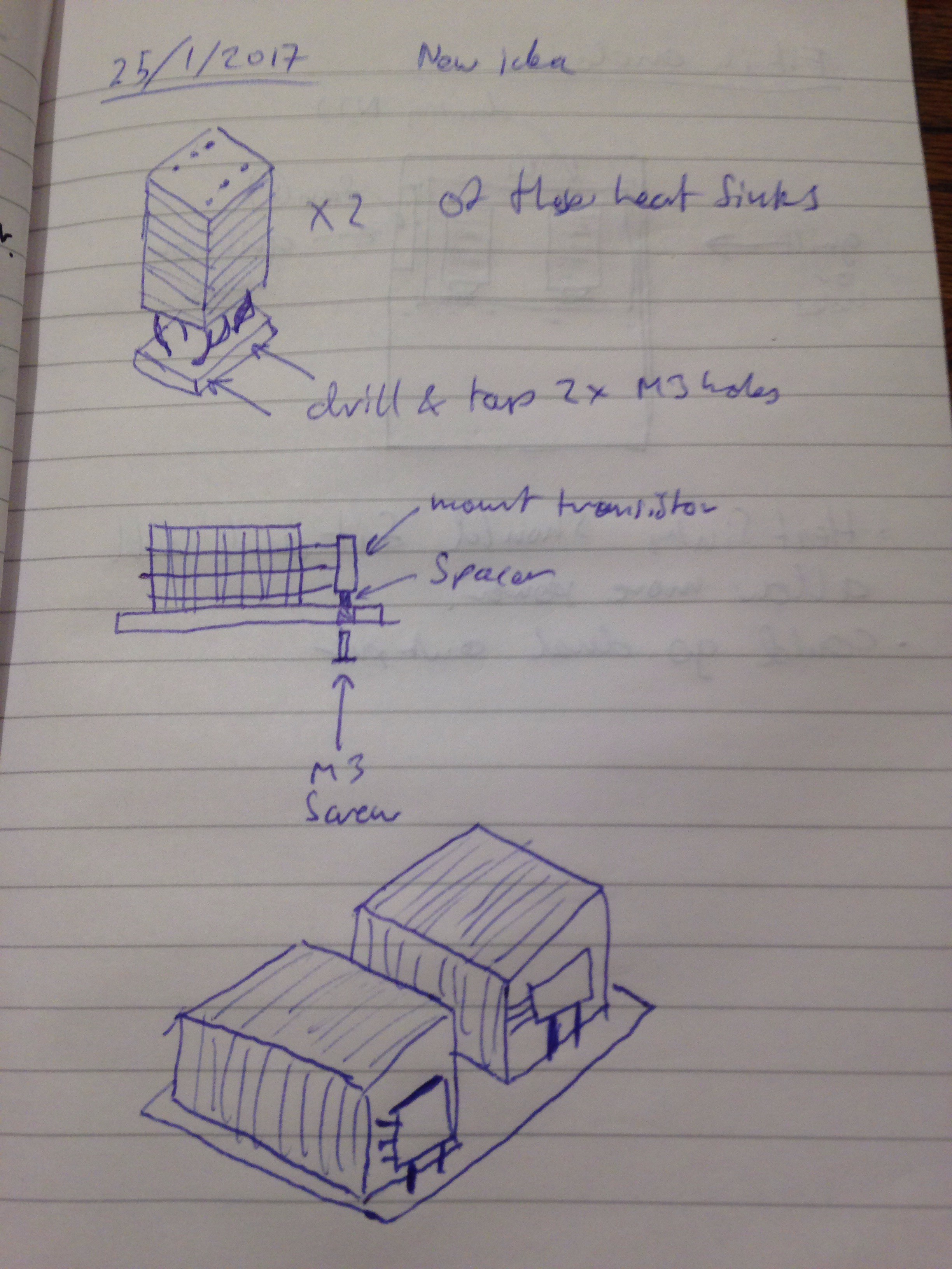
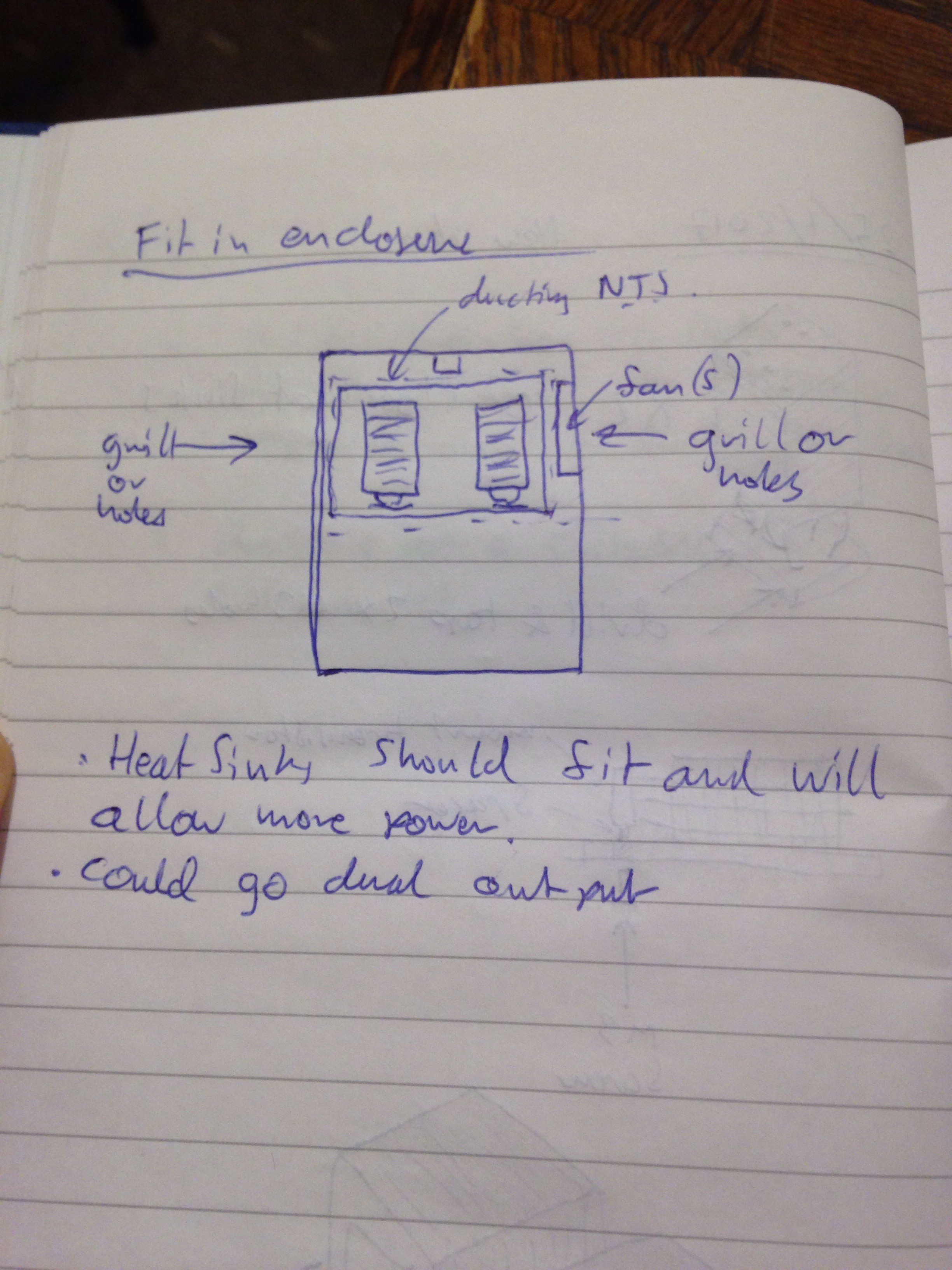
- Implement a new pair of heatsinks I've found:
![]()
![]()
- Even though I don't doubt that they could handle 60W, I'd like to determine their thermal resistances.
Right...you're up to date now!
Discussions
Become a Hackaday.io Member
Create an account to leave a comment. Already have an account? Log In.