 Jbarlow1007
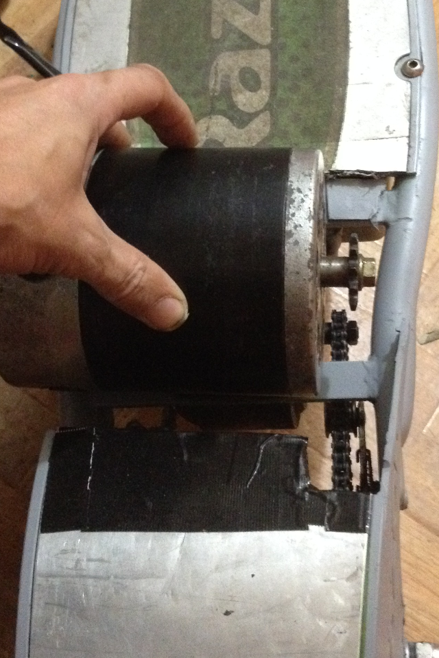
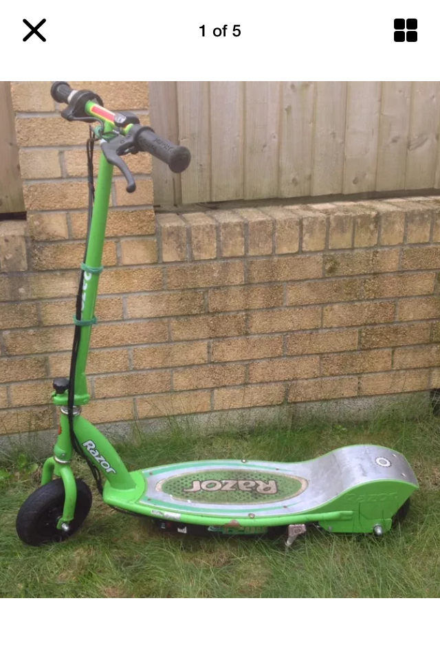
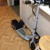
My razor E200 now it's the way it shod be
Already have an account? Log in.
To make the experience fit your profile, pick a username and tell us what interests you.
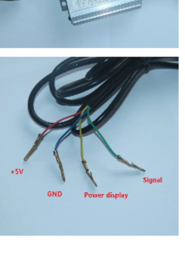

I have done this but now i am scared that the wiring is ok . The charging ports are they safe . Having two chargers one doing the 24v & other 12v now the Conroller duz the cel charging thing , but it's only wired up to The - to the battry & the red + is going to the switch so it's not really controlling things. Only help on this plus do I need to run a relay or a fuse on this . It's the only way Ican get a controller to run . Iv tryed 36v ones and they don't work . & the seller just tells me that it's me that plunged it in wrong . What can I do . I got a 3pin twist grip bit never got it to work . If anyone Nos how to make the 3wire red/blue/black/ & yellow if there is a way to put it to the razore200 4pin ends then let me no.
p.s you will need to remove the kickstand and the mounting bracket when fitting a bigger motor . I put a 350w 24v and it needed moving .
Plus alway make sure u go over the wiring as its best to get it right the 1st time. I will put the wiring up on how I made it go from 24v to 36v. It best I found to g mo from 24v to 36v as overvoulting with 3 battrys is gave me more room , 4 would give me no room . 48v would be cool but no room. Plus running on a 24v controller meens switching to 36v is not hard . But u run it on a 36v controller and as soon as u go to 24v it will not run as the 36v controller has a cut off at 32v .

thank u . It seem to swtch it to 24to36v no problem . I can take the 3d battey off and charge it . But would be nice to keep it looking good . But safety has to come into it. It's not charging though the controller ,so am hoping the 24v charger will just charge the 2 battrys & the 12v will do the other with out taking the battey out each time . I will try the LED light
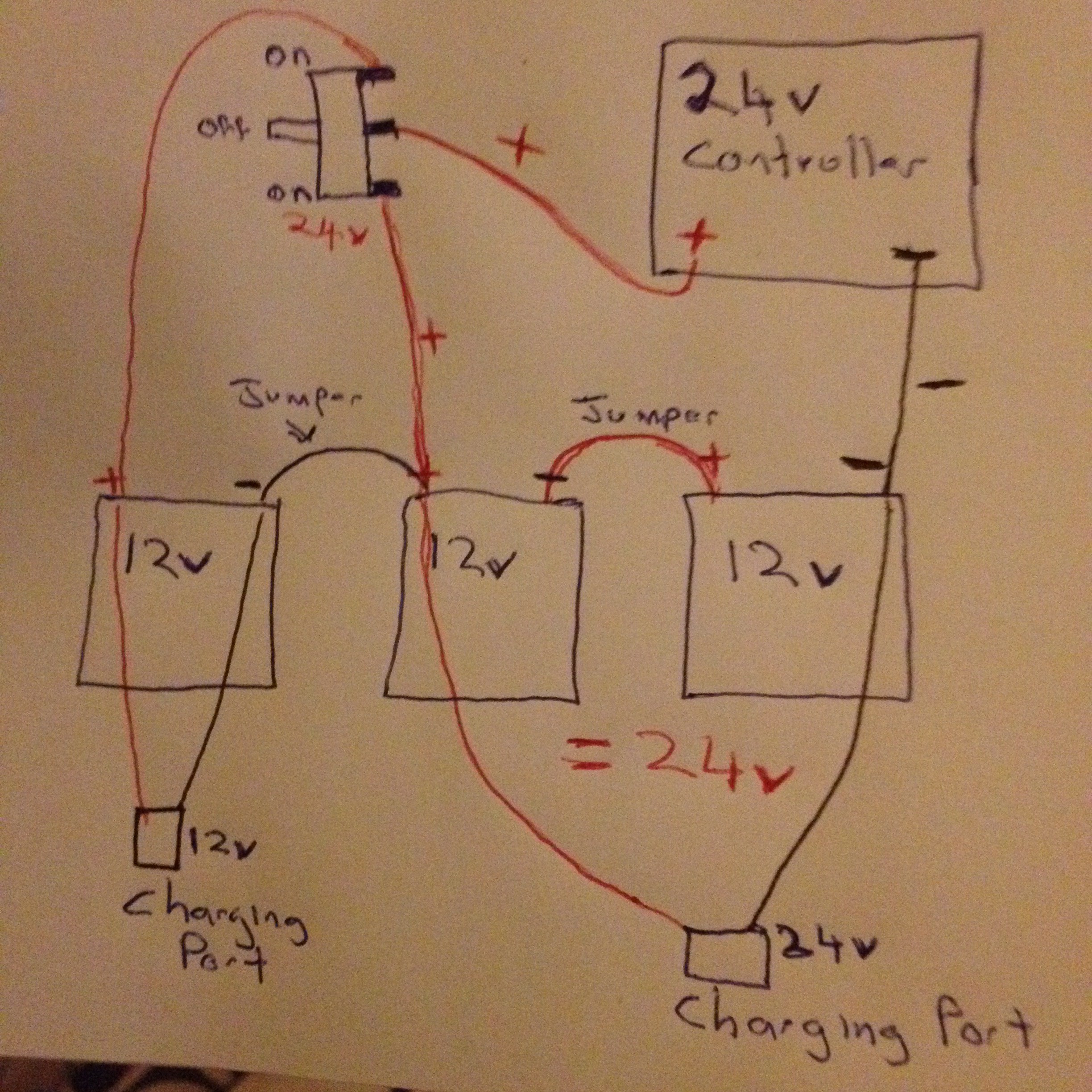
need help the charging the two12v/= 24v battryes to one charger the - will go to one end & + to the other battrey end .
& then the 12v battery will be charged by a 12v charger . But will it work . I no the 24v I can it could charge them by the controller as its going into that . & the other 12v I can take out to charge . But if I wire it all up the way the pic shows me will it no work . & if not why . Is it the way all the wires r wired up so if I charge the 24v at the same time as the 12v will it go bang . Please help me . I am using a ( on off on ) SPDT switch and the + from the contoller gos to the middle of the switch . The 24v + gos to the bottom end . & the 12v + that makes it up to 36v to the + to the top of the switch Z can anyone help me and let me no it will work . I am about to charge all the battrys tomorrow so I need to no .
can I ask u did u see the wiring pic I put up. Would that work. Two charging ports one 24v for two battrys & one 12v for the other. The controller is only wires black - to the Battey & red + to the switch SPDT switch midday . So when off the charger gos to the two battrys .ok the 2d Battey wired up making 36v but the red+ gos to the top 36v switch . So not on connected to controller . Please look at my pic of the wiring up and tell me what u think
Well, you haven't characterized your controller or your switch. I would suggest drawing seperate circuit diagrams for each of the possible positions of your switch. Then draw loops how you think the current will flow.
I wouldn't suggest Fritzing to anyone. But if it makes it more accessible then by all means try to draw your diagram using that tool. (Where to get and how to use.)
Use that tool to try things out and see if you got it right. (Still no guarantees) Later on try KiCad. But keep things simple at first. Fritzing also allows you to simulate your setup to a very limited degree. In your case I think it will help you get a feel for what you are doing.
I understand the desire to just hook things up and see if it works but you can lose a controller, battery or motor if you get things too wrong. Then when you call the manufacturer of the controller with a question you'll get a terse answer telling you it's your fault.😀
yep had that with other controller 36v 800w one but I did do it right & they still told me it's my fault . So I sm trying to do it this way. So the pic I put up will not work . 24v switch to 36v well I see not work I no it works as Iv had it running on 24v then switch 36v but the charging . How do I get around it. Will two chargers not work. And if not how can I get it to charge them.
thank you for that link . I try and do what I got planed on there . & then see what happens . I am no expert When it comes to this stuff but I love to make things work & taking things apart & seeing how they worked when I was 12years old & well up to now lol 42.but no wear near the no how on the things you do . When I was 12 I taken off my dads petrol lawnmower and cut a V shap into the back wheel of my skateboard & used the belt to drive the back wheel . It was the 1st ever petrol skateboard lol . But now I love scooters,iv seen some with the right wheels 10" 12" and the right gears iv seen them go 35mph plus. But anyway thank you for helping & taking a interested in project .
it's a razor e200/300 controller can put pic up . Plus switch is a SPDT on off on . But it only has 3 ends to it top middle bottom , I seen the ones that have 6 to them, so say u put the main + from the controller to the middle one u an out a jump wire to the other side and so on .so u put the 36v battey 3rd one to the top of switch , & the 24v 2sec battry to the bottom switch . But I think what u r saying is with that other switch wear the wire say from the bottom 24v end then across to the other side of the switch if it had one then flipping the switch down to the 24v mode would the make a 24v charge is that about right
it's a razor e200/300 controller can put pic up . Plus switch is a SPDT on off on . But it only has 3 ends to it top middle bottom , I seen the ones that have 6 to them, so say u put the main + from the controller to the middle one u an out a jump wire to the other side and so on .so u put the 36v battey 3rd one to the top of switch , & the 24v 2sec battry to the bottom switch . But I think what u r saying is with that other switch wear the wire say from the bottom 24v end then across to the other side of the switch if it had one then flipping the switch down to the 24v mode would the make a 24v charge is that about right
I don't mean to intrude on your project design. It's probably not a good idea to have your controller in-circuit while you're charging. Not too many controllers will tolerate that. It depends on your controller of course but I can't think of a scenario where you would need to have both the controller and the charger connected at the same time. Sounds like a good way to make blue smoke. The 24-36v option may seem like a good idea but you will have battery issues if you run it that way for long. The problem when using more than one battery is making sure they are load balanced otherwise you will shorten the life of the batteries if they are lead acid or cause a fire if they are Lithium.
If you have things you would like input on post the questions in your log. We've got a lot of helpful people here as long as you avoid certain subjects ;-)
 steamboat
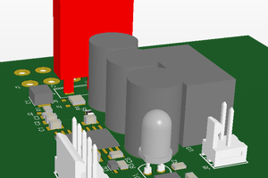
 ARBartz
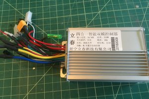
 Jorj Bauer
 Ampeater
I owe you an apology. I thought Fritzing had a built in simulator (the only reason I suggested it.)
It doesn't.
Here's a link to a browser based simulator.
https://www.partsim.com/
Simulate the controller with a voltage controller. Simulate the motor with a light. Then try different configurations using the same switch.