Matthias Kesenheimer
-
July 30 2025
07/30/2025 at 08:53 • 0 commentsOne Hertz Challenge
I decided to submit this project to the "One Hertz Challenge", as the project is perfect for this. Not only does voltage glitching have to do with very precise timing, the Pico Glitcher is also able to generate very precise and arbitrary pulses thanks to the multiplexing (https://fault-injection-library.readthedocs.io/en/latest/multiplexing/) and pulse shaping (https://fault-injection-library.readthedocs.io/en/latest/pulse_shaping/) methods.
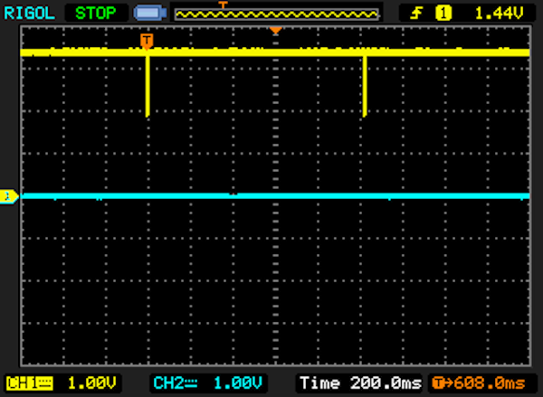
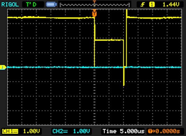
The following figures illustrate the voltage step emitted by the multiplexing stage of the Pico Glitcher each second. This voltage step can be configured arbitrarily. For instance, the voltages and duration of each step can be set.
![]()
![]()
Only a few lines of Python code are necessary to emit this voltage step with the Pico Glitcher:
import time
from findus import PicoGlitcher

glitcher = PicoGlitcher()
glitcher.init(port="/dev/tty.usbmodem1301")
glitcher.rising_edge_trigger()
glitcher.set_multiplexing()

while True:
    mul_config = {"t1": 10_000, "v1": "1.8", "t2": 1_000, "v2": "GND"}
    glitcher.arm_multiplexing(0, mul_config, "VI2")
    glitcher.reset_target(0.01)

    try:
        glitcher.block(timeout=1)
        response = b'Trigger ok'
    except Exception as _:
        response = b'Timeout'

    print(response)
    # wait for one second
    time.sleep(1)
First, the PicoGlitcher class of the findus library (https://pypi.org/project/findus/) is imported. The glitcher object is initialized by the subsequent commands. Then, the multiplexing configuration is generated. Up to four different timings and voltages can be configured at this stage. Finally, the glitcher is armed, meaning it waits for the trigger condition to be met. When a rising edge is detected on the TRIGGER input, the voltage step is emitted. The scripts wait for one second until the next configuration is generated and submitted to the glitcher.
This shows, how few lines of codes are necessary to generate arbitrary voltage steps. This can be taken to the extreme with the Pulse Shaping method. Meaning not only any voltage levels, but any voltage curve can be generated.
-
January 02, 2025: Genetic Algorithm
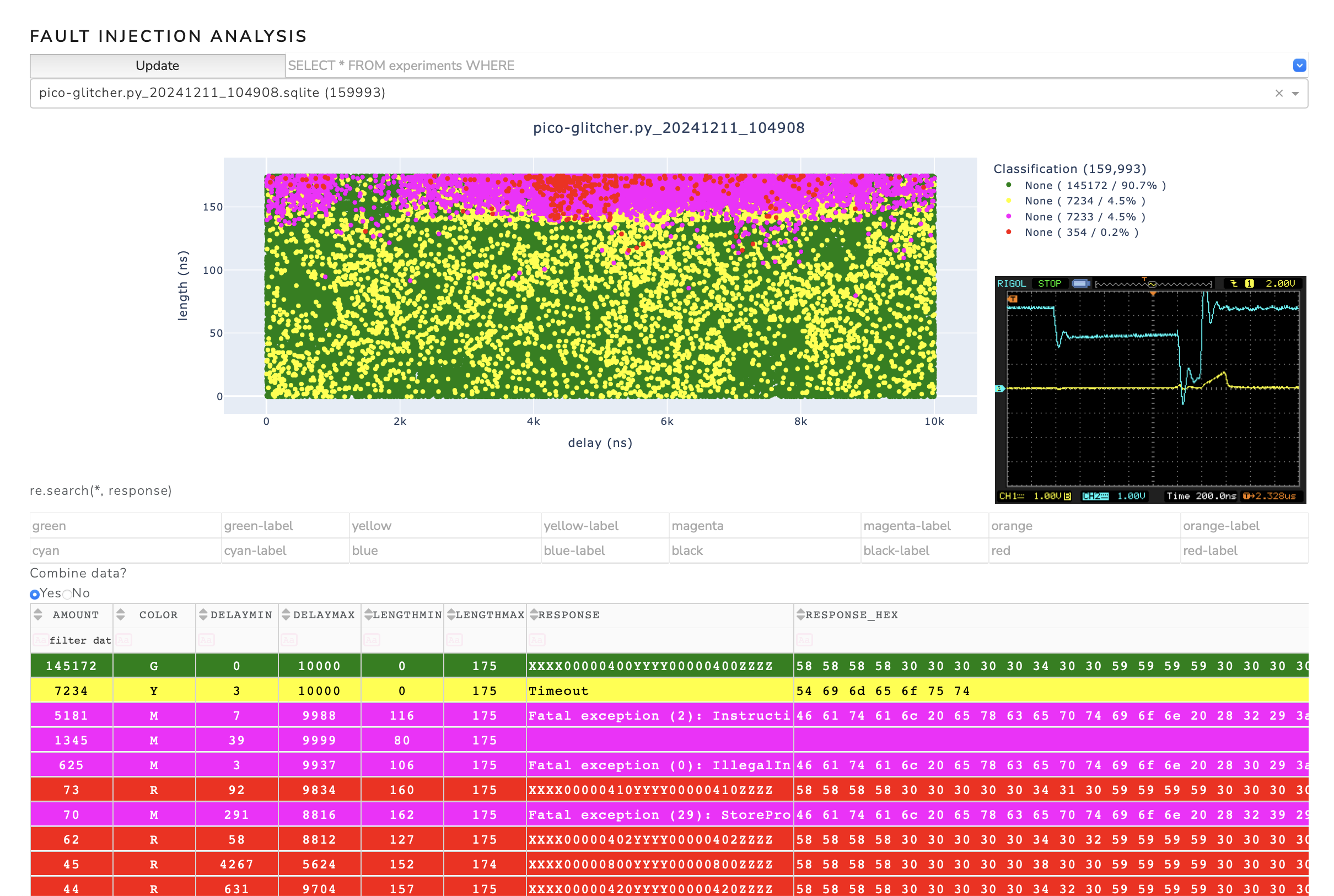
01/02/2025 at 14:54 • 0 commentsIn some cases, finding the parameters of a successful glitch can be quite tedious. Especially if the possible parameter space is large (see multiplexing and pulse-shaping). Therefore, the search for a suitable parameter point must be done somewhat more intelligently than with a brute force approach.
In the case of the fault-injeciton-library, a genetic algorithm has been implemented that can be used to search for the optimum parameter points.
If implemented correctly (and with a suitable configuration of the
OptimizationController) you should expect clustering experiments around successful glitches. See the figure below for an example output of a glitching campaign. In this case, the ESP32v1.3 was glitched via the multiplexing method. More details can be found here.![]()
-
January 2 2025: Components overview of the Pico Glitcher v2
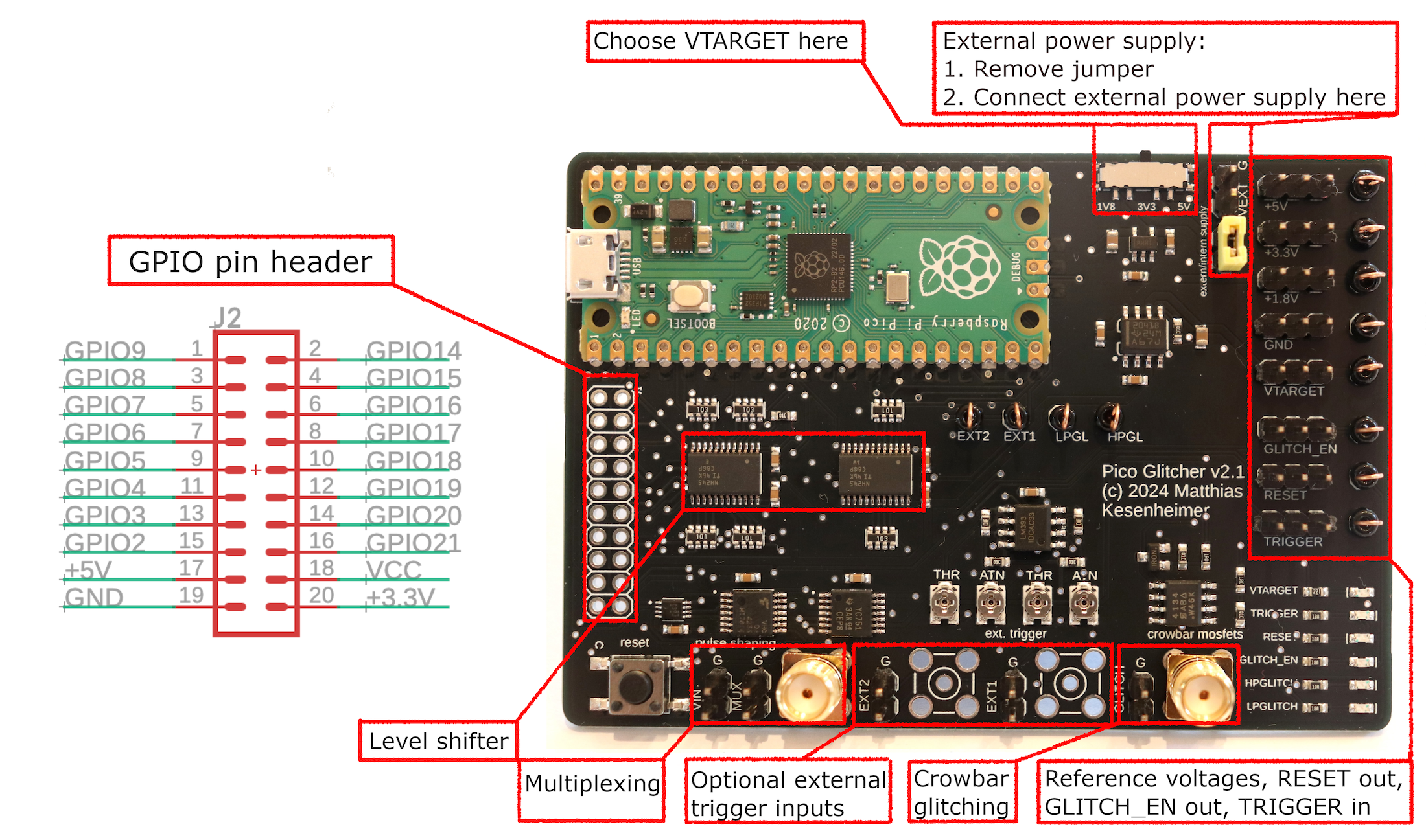
01/02/2025 at 14:39 • 0 commentsThe hardware is based on the Raspberry Pi Pico, two high-power MOSFETs for crowbar glitch generation, and two level shifters to ensure compatibility over a wide voltage range. A newly designed input stage (EXT1 and EXT2) can be used to filter out noise and other disturbances via adjustable Schmitt Triggers. The multiplexing output can be used to quickly switch between up to four different voltage levels and to supply the target board with power.
The second revision of the Pico Glitcher can also be modified to suit your needs. The Pico Glitcher v2 is built from the following components:
![]()
-
December 15 2024: PicoGlitcher v1 sold out!
12/15/2024 at 16:13 • 0 commentsDue to the high demand for the Pico-Glitcher, the first batch has been sold out. Many thanks to everyone who has supported me by purchasing a Pico-Glitcher. I am currently planning the second hardware version of the Pico-Glitcher, which will have some new features. For example, in version 2 it will be possible to define the glitch pulse shape by different voltages at certain time intervals (so-called pulse shaping). In addition, two separate inputs with preamplifier and Schmitt trigger will facilitate triggering to different voltages. Stay tuned!
-
October 29 2024: Project Documentation
10/29/2024 at 20:37 • 0 commentsThe documentation of the software and the hardware is now available under https://fault-injection-library.readthedocs.io/en/latest/.
Any feedback is appreciated!
![]()
-
September 12 2024: Assembly of the updated PCBs
09/13/2024 at 07:54 • 0 commentsAfter ten days I received my order from JLCPCB. As mentioned in the previous project log, generating the design files (gerber, CPL and BOM) was fairly straight forward.
The finished PCBs are of high quality. I could not find any errors and the components are perfectly placed and soldered. I am really happy with the way the PicoGlitcher PCB turned out.
![]()
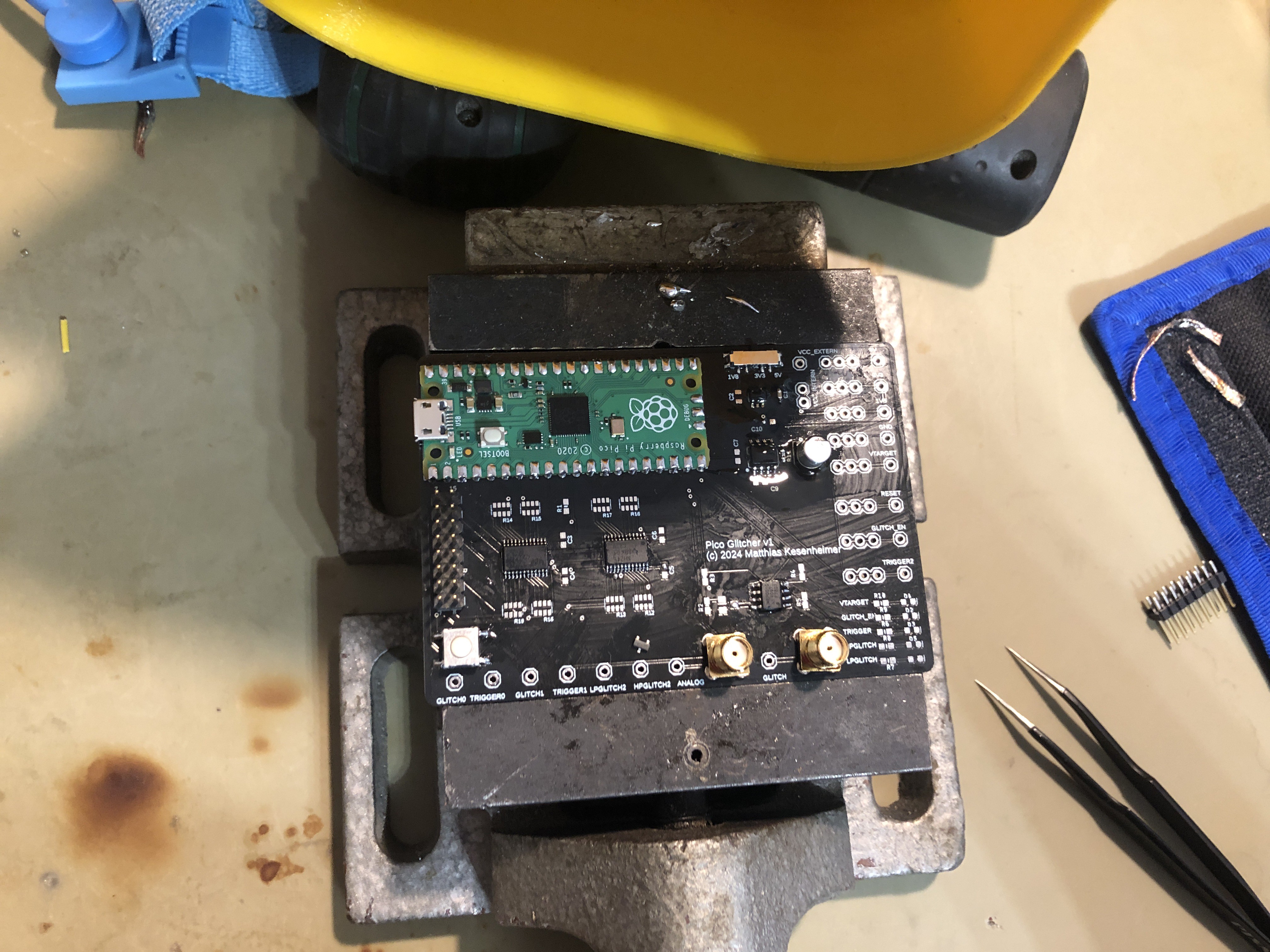
The next step was to solder the rest of the components onto the board. For example, the Raspberry Pi Pico and some other through-hole components have to be soldered by hand. The finished board can be seen below.
![]()
The new design also works flawlessly. I could generate reproducible glitches on a STM microcontroller within a few minutes.
![]()
-
September 3 2024: PCB updates
09/13/2024 at 07:33 • 0 commentsFirst of all, the design of the PicoGlitcher is good and I have not found any major flaws yet. The PicoGlitcher works.
However, I have noticed that some of the PCB markings are hard to read, and some are even missing. The component placement is also not optimal, so I decided to update the PCB files. Soldering the small SMD components by hand was difficult (for me at least), so I decided to give PCB manufacturing with component placement a try.
I made a few changes to the design files, picked all the components from JLCPCB via the Assembly Parts Lib and uploaded the new gerber files. In order to automatically generate the BOM and the component placement file (CPL) in Fusion360, I used the library jlcpcb-eagle. With the gerber, the BOM and the CPL files ready, I was finally able to submit my order to JLCPCB. All the relevant files can be found on my github page.
I was surprised at how easy the whole procedure was. The JLCPCB parts library is huge and if an exact part is not available, there is always an alternative. What's more, every step of the process is easy to understand. The component placement is displayed in an online tool that allows you to check that all the components have been placed correctly. Manufacturing and shipping was fast. I received my order within ten days.
![]()
-
July 8 2024: PicoGlitcher in operation
08/05/2024 at 19:01 • 0 commentsHere you can see a video of a running glitching campaign. The target gets reset, a glitch is emitted and the status of RDP is checked.
-
July 8 2024, later this day: Glitches!
08/05/2024 at 18:53 • 0 commentsI am practiced in doing fine soldering work, but soldering the selected SMD components was nevertheless challenging. In the end, however, the soldering work was successful. The PicoGlitcher is working as expected and I am able to glitch targets. For a test if everything works, I ran a glitch against an STM32F4 microcontroller. Although RDP level 1 was activated, the target responds with an "ACK" after a few attempts when accessing the flash memory in bootloader mode.
The PicoGlitcher v1 actually works!
![]()
-
July 8 2024: Assembly
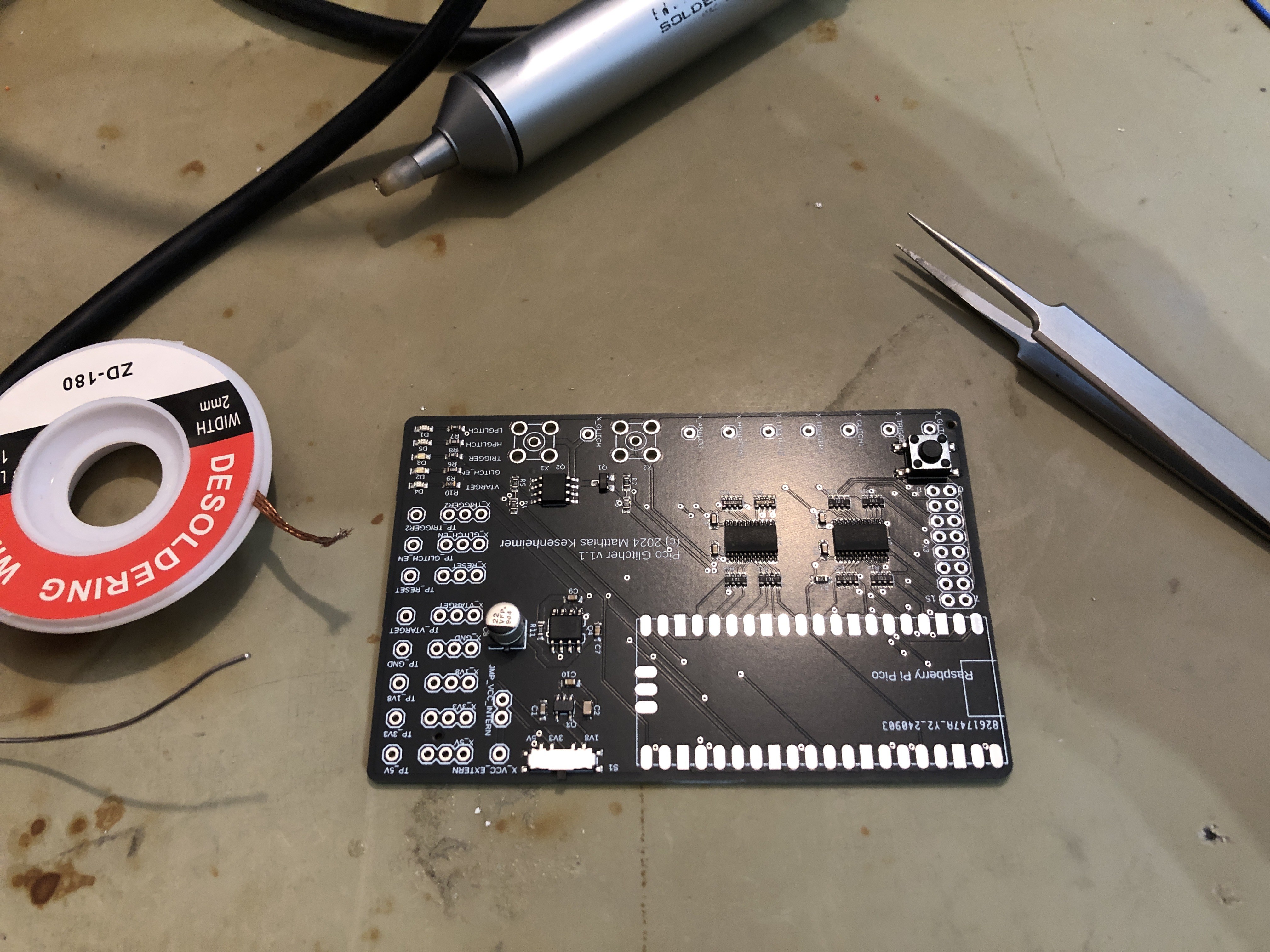
08/05/2024 at 18:46 • 0 commentsAll the parts have finally arrived and I can now assemble the circuit boards. The boards look amazingly well made, all the tracks are perfect and there are no visible faults. The black boards stand out really nice.
![]()
Hacking MCUs with the Pico Glitcher v2
A hardware device to carry out voltage glitching attacks against microcontrollers with a Raspberry Pi Pico