 Bruce Land
-- Audio loop-back configuration
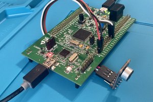
The University Audio Core supports audio input and output at various rates and resolutions, and exposes the data on the Avalon bus. The Bus Master page explains the basic connections. There is a control word, four 8-bit FIFO fields (in/out, left/right), and left/right data registers. The lef/right data registers are read/write. Properly configured, a read to the data register gives data from the audio ADC, while the write to the data register outputs to the audio DAC. The Audio Configuration module needs to be modified in Qsys for proper operation. Double-click the module name in Qsys to open a dialog box. In the dialog box, set up: (1) Audio in Path: Line In to ADC; (2) Check Audio Out-Enable DAC Output; (3) Uncheck Audio Out-Microphone Bypass; (4) Uncheck Audio Out-Line In Bypass
Generate the Qsys design, and recompile the project. This project just loops the audio input to the audio output, except that if you turn switch zero on, a tone is generated on the left channel with a frequency proportional to all the switch settings. You have to press reset (button zero) after you load the design to start the state machine. (top-level module, ZIP of project).
-- A slightly reorgnized design separates the audio waveform generation and connections from the audio interface bus-master state machine. The DDS and loopback connections are separate from the generic bus read/write. (top-level module)
-- Audio Filtering
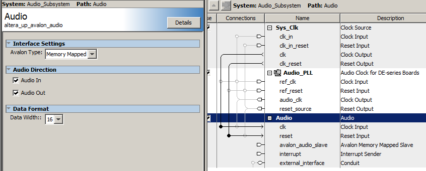
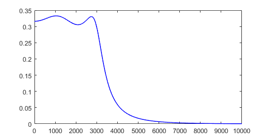
The audio codec settings were changed in Qsys to enable 16-bit, 2's complement signals, to match the filters which had already been written for the DE2. Changing the codec bit-width requires an edit (in Qsys) to both the AV_config dialog box, then open the Audio Subsystem and edit that dialog box. The test filter was a 2-pole Butterworth, bandpass filter at 3000 to 6600 Hz, with a normalized freq 0.125 to 0.275, and Peak at 0.2 which is 4800 Hz. Actual measured peak is 4740 Hz. The matlab code which writes the Verilog filter definition is also at the end of the top-level file. (top-level module, ZIP of project).
-- Audio Filtering with decimated sample rate
Low frequency filters can be unstable with limited corfficient bits. A scheme to drop the sample rate to 8KHz (for voice) low pass filters the signal so that frequencies above 4 KHz are attenuated about a factor of ten. Then the sample rate is lowered by taking every 8th sample out of the lowpass filter. This example compares two 300 Hz center frequency, Butterworth filters, with a design bandwidth of about 100 Hz. One is running at a sample rate of 48KHz, the other at 8KHz using input from the decimation filter output. (top_level module, project ZIP). The actual performance of the two seems very similar. Actual center frequency is 300+/-3 HZ. Bandwidths are similar, with half-amplitudes at about 225 Hz and 420 Hz. Filter headers were generated using a matlab script to translate filter coefficients from floating point to 2:16 fixed point. Another script was used to design the decimator filter.
 BleakyTex
 Paul Stoffregen
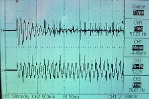
 zpekic
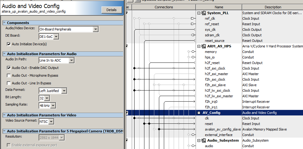