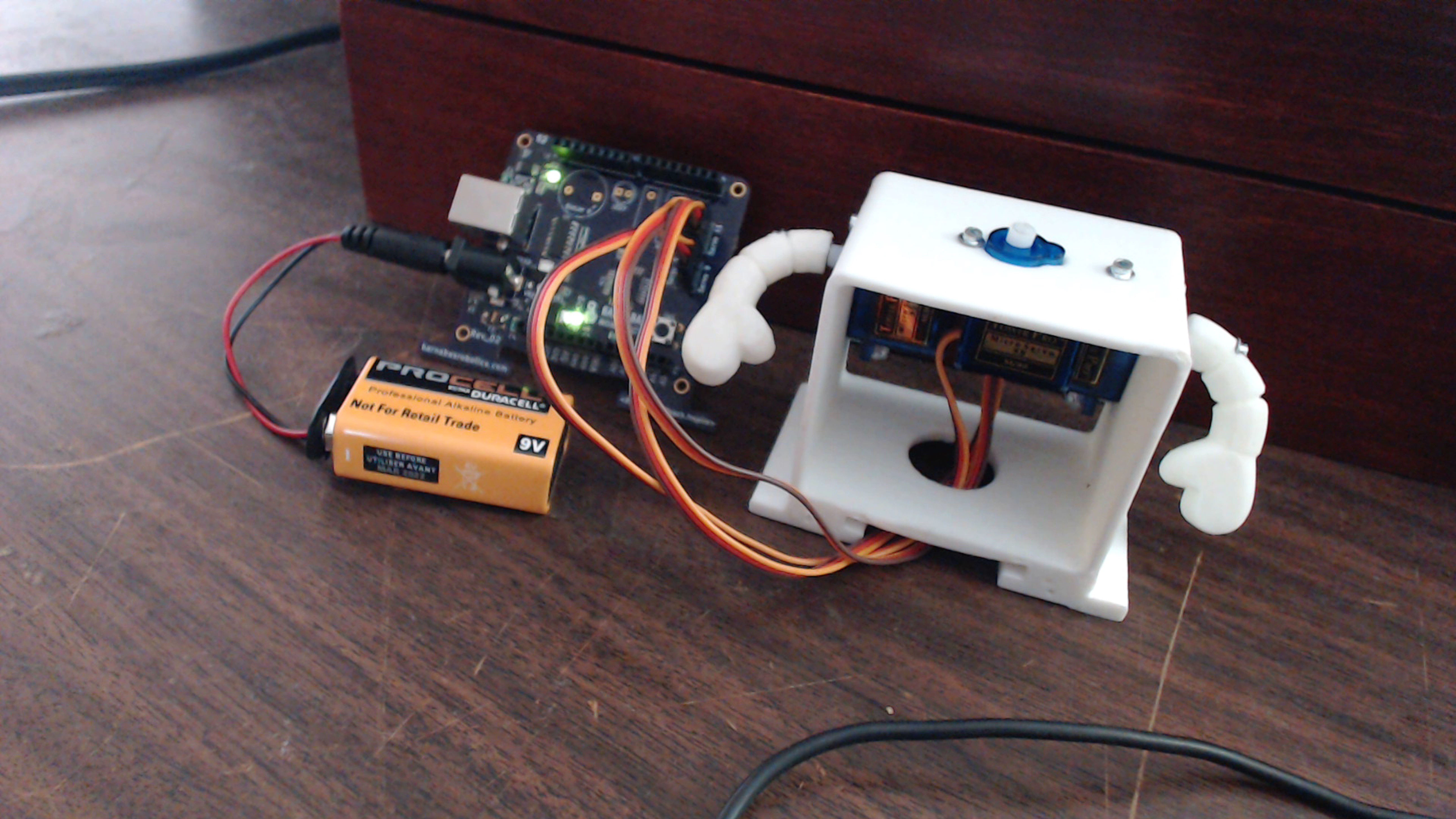
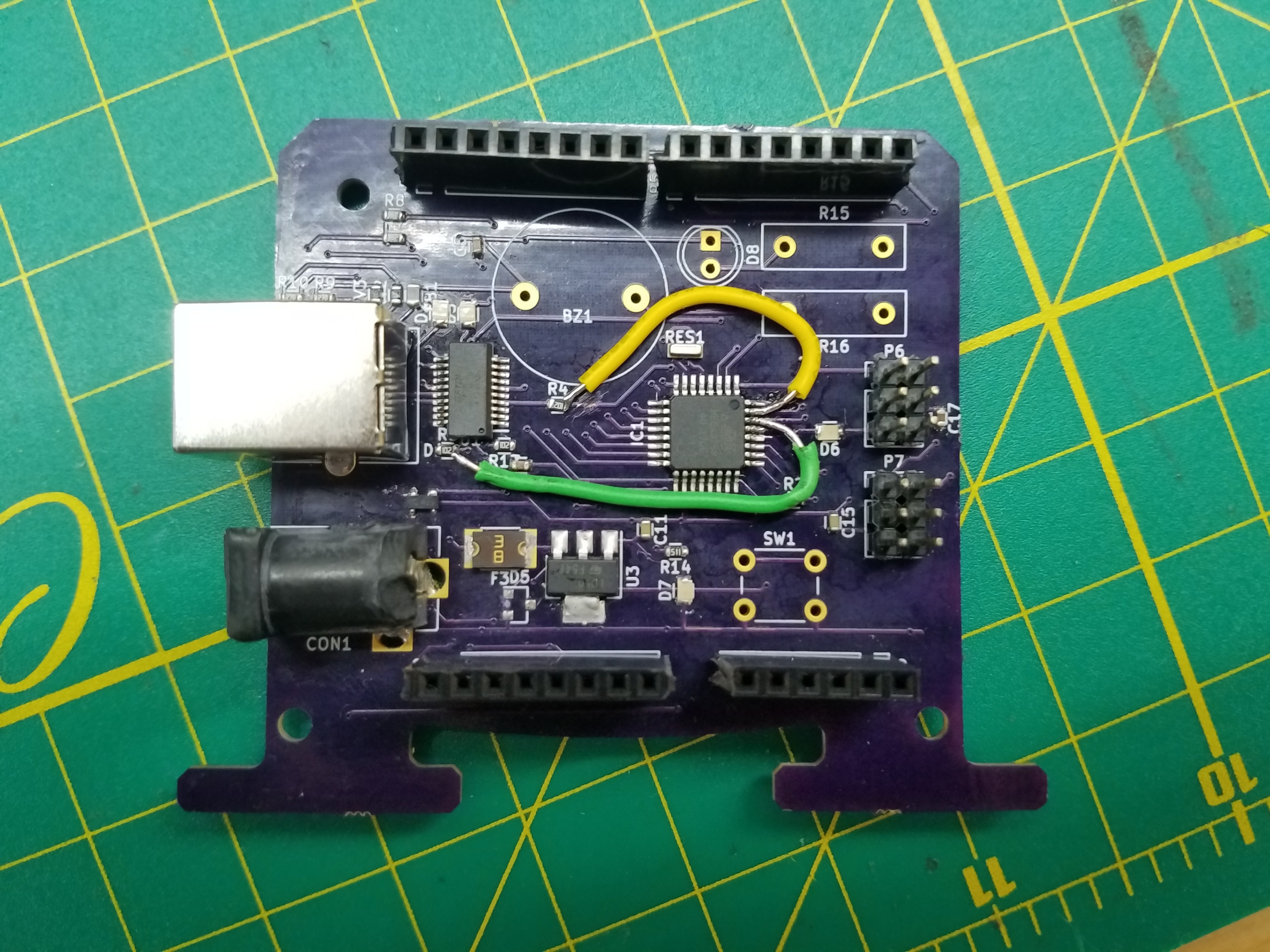
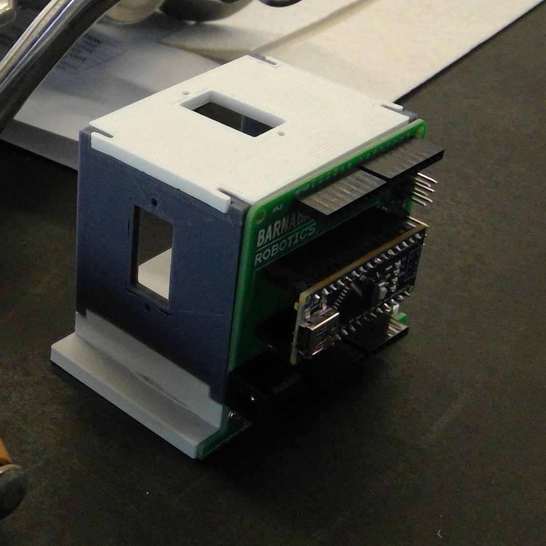
Close
0%
0%

Barnabas-Bot

An open-source educational robotics project that inspires elementary and middle school kids to invent through building their own robot

Similar projects worth following
This project started in May of 2014 by asking one question - how might we bring joy and purpose into technology? As we interviewed hundreds of teachers, parents and engineers, we got the idea to build simple robots with kids. We wanted to bring kids through the process from ground up, rather than connecting off-the-shelf parts.

This was the inspiration of our first Barnabas-Bot. We brought it to a small classroom in Pasadena, and have since iterated the design through hundreds of hours of classroom testing. The project mainly consists of CAD design, 3-D printing, software and hardware design.

We are continuing to fine tune our open-source Barnabas-Bot program to make it more accessible to students across the globe. We are also working on an open-source curriculum that will help any elementary or school teacher inspire young minds through our kit.

barnabas-bot-body-master.zip

Solidswork files for 3-D printable Barnabas-Bot. Version 2.2.

x-zip-compressed - 13.12 MB - 01/29/2017 at 01:56

Download

Edward_BarnabasNoggin_RevC.zip

EAGLE file for Barnabas Noggin daughter board for Arduino Nano -- REV C Created by Vincent Kok.

x-zip-compressed - 1.43 MB - 01/29/2017 at 01:54

Download

ENG-NOTEBOOK-16-SESSION-1.02.docx

Sample engineering notebook for Barnabas-Bot Class

document - 4.19 MB - 01/29/2017 at 01:52

Download

  • 1 × Barnabas Noggin (or Arduino-Uno compatible board) Amazon keyword search: Arduino Uno Compatible Board
  • 2 × 4700 Ohm Resistors (Thru-Hole Type) Amazon keyword search: 4.7K Ohm Resistor
  • 2 × 470 Ohm Resistors (Thru-Hole Type) Amazon keyword search: 470 Ohm Resistor
  • 1 × 170 point mini-breadboard Amazon keyword search: mini breadboard
  • 1 × 5mm LED Amazon keyword search: 5mm led 3v

View all 17 components

  • Success* at last

    eric12/02/2017 at 18:05 0 comments

     I got the board working;

    For the most part at least. The board gets power, can communicate via usb, accept code, and power components such as motors. However there is still a problem. That being the board's inability to receive power from USB. I think that the reason for that is a fundamental misunderstanding of p-mosfets.

        I am well aware that p-fets act as inverters, only turning the channel on if the gate is low. However when routing the board I forgot that current only flows from source to drain in a p-fet. Thus the power management subsystem that allows the board to receive power via USB is essentially backwards.


        So I need to Mcgyver the board in a way that allows me to verify this. You will probably be hearing from me again soon.

    Till next time,

    -Eric

  • Same ol'

    eric12/01/2017 at 00:53 0 comments

    Hey guys,

        Quick update on the Barnabas noggin. I finished soldering it together today and, surprise surprise, it doesn't work. Not "I can't put code on it", more like "It doesn't receive power whatsoever". But, after a few hours of debugging I found the culprit;

    This barrel jack was wired in the way above because I assumed pin 3 was internally connected to pin 2, AND NOTHING ELSE. In other words, I assumed the following schematic was an accurate representation of the barrel jack;

    As it turns out, pin 3 is also internally connected to pin 1 in some way. So the layout is shorting the power source completely. After chopping off pin 3 on another jack and placing it onto the board, I confirmed that to be the case.

        In addition to that problem there was some poor soldering that I am in the process of touching up. I'll keep you guys in the loop.

    Till next time,

    -Eric

  • One step forward, one step back

    eric11/10/2017 at 20:10 0 comments

    Hey everyone,

    Long time no see guys. I just thought I'd give you an update.

        Since I last checked in there have been a few changes. First being the serial chip that we were using in the prototype, an FTDI chip, was replaced by a ch340ser chip, mostly due to reduced cost. However this lead to a pretty stupid mistake on my part which ended up halting progress for a couple weeks. I had decided to use the 340t version of the chip, but for whatever reason I used the 340g pinout when editing the schematic. Essentially, my schematic includes a part which doesn't exist.

        We have since fixed this in the schematic/PCB and have new boards on the way, but That is not the only change I have made. In addition I have removed the diode that was previously between the external reset pin and the reset pin on the atmega328p. For some reason that diode was making the process of burning the bootloader onto the atmega chip very difficult. My guess is that the voltage drop from the diode was causing the reset to not trigger on the chip, but I could be wrong.

        You can see where the diode was removed in the schematic above.

        I don't want to speak too soon but I've got a good feeling about the new version of the board. Hopefully next time you hear from me I'll be bringing good news.

    Till next time,

    -Eric

  • In the nic of time -Eric

    eric07/02/2017 at 22:51 0 comments

    Hey everyone!

    As you know the Design Lab residency has officially ended, and as of last week I was scrambling to get the noggin I have been working on for the past four months fully functional.

    Luckily on Friday, literally the last day of the residency, Ed and I were able to get the Barnabas noggin to function as intended. The two issues from last week, not getting power from the barrel jack and the board not being recognized by Arduino (or my laptop in general), have been fixed.

    Like I suspected, the board was not getting power from the barrel jack due to a burnt out diode. As soon as that was replaced the board received power as expected. The other issue it turns out was due to a very silly mistake on my part. I had linked the Tx of each chip to each other and the Rx of each chip to each other when they should be swapped. Luckily some McGyvering let us remedy the situation;

    So what comes next? Well I don't intend to stop giving updates any time soon, as there's a lot that still needs to be done before this board is truly ready for production.

    So until next time,

    -Eric

  • IT IS ALIIIIIVE!! -Eric

    eric06/26/2017 at 22:50 0 comments

    A lot has happened since I left you guys last. Some bad, mostly good. First and for most the board has been completely soldered;

    ....and it looks beautiful. As far as the functionality of the board goes, it's not all sunshine and rainbows. I can't power the board from the barrel jack and my computer will not recognize the board, so I do have some things to troubleshoot. However, I have successfully burned a bootloader to the board and managed to download code to it in a round about way. I also can power it externally or via the USB jack. So without further to do, here is the culmination of my success;

    I know it doesn't seem like much BUT IT WAS HARD FOR ME SO BACK OFF!

    In addition to this I have continued to make revisions to the next version of this board, including ascetic changes (I did not care about how the last version looked at all). That mostly just means actually numbering pins, putting our name/website/slogan on the board, check it out;

    If you look in the upper right hand corner, you can see we even fit our logo on it;

    So I'm gonna keep working on it, hopefully by next week I'll have most of the problems ironed out.

    Till next time

    -Eric

  • Milestone -Eric

    eric06/17/2017 at 19:31 1 comment

    My first PCBs have arrived!

    So I should be excited, right? Well, hold on. Here is the back side of the board;

    See it?

    Look closer;

    ........... Not my finest moment, that's for sure. So I'm left with with the task of McGyvering a way to solder a cap, and then a voltage reg. on top of it. Afterwards HOPEFULLY it just works.

    In addition to that I am working on the next iteration of the board. I'm considering all of the problems the current board has, coming from the obvious ones (see above), the mechanical ones that will make it difficult to combine this board with the body Ryan is developing (current one fits but could stand to be .5mm to 1mm wider), and the manufacturing minded ones that will inflate the price of the board (such as having components on both sides of the board as opposed to one).

    Till next time

    -Eric

  • Getting Somewhere -Eric

    eric06/10/2017 at 01:26 0 comments

    Hey guys,

    Last time I talked to you I was struggling to burn a bootloader onto a blank atmega328p-au chip. My guess was that the connections on the FR1 board that I had milled out were bad, particularly the ones on the crystal. I tested this hypothesis this week by creating the same circuit on a breadboard, using a through hole version of the crystal I was previously using and a FR4 version of a tqfp32 breakout ( I keep destroying the traces on the FR1 boards when I solder). The whole situation ended up looking something like this;

    So, in the end, I finally did get the bootloader onto the blank chip. This would seem to support the idea that the previous problems were related to poor soldering on my part rather than poor engineering on my part, what a relief.

    With that, I felt confident enough in my design to finally order boards from OSHPark, which should arrive next week!

    Till Next Time,

    -Eric

  • Please just work -Eric

    eric06/03/2017 at 21:21 2 comments

    Hey guys,

    Since I last talked to you I have still been trying to troubleshoot the ATmega328p, in particular burning a bootloader onto it. I successfully burned a bootloader onto another uno using an uno, which I just did as a sanity check to make sure I actually knew how to do that.

    I also made a "breakout board" that essentially just had the bare minimum needed to burn the bootlosder onto the chip;

    Unfortunately this did not work either. I suspect that the crystal is not properly soldered on to the board (it is an incredibly small component). Next week I need to thoroughly probe the traces to be absolutely sure that the issue is not there.

    I have also ordered additional resonators to see if that may be the issue. One is essentially the same crystal I am using but is a through hole component, which will allow me to take the variable of soldering out of the equation. If I can successfully burn a bootloader using that crystal it will tell me that my current issues lie with the soldering. Whether I am damaging the component when I solder or am simply creating shorts, I am unsure. Hopefully the additional probing will give me additional insight.

    Till next time,

    -Eric

  • Time to Shape Up

    Ryan06/02/2017 at 21:07 0 comments

    Hello people of the internet and ....

    Today we will talk about the state of the body. Unfortunately, due to personal issues like school. i was unable to reach that tooling stage of the body that i wanted but fear not. I have fixed the issue of that pin issues fitting with the rest of the body. The crazy solution that i came up with is the same as the bottom part. I created in indent so that the pins on the top part of the PCB will no longer be hitting it. Allowing free movement to the desired places.

    Additionally, it is time to let our body go on a fat reduction. Meaning, we need to make the printing process of our robot much faster since it takes so long to print already.

    We may never find out if this will work by keeping its integrity but hey, until next time.

  • BOOM!

    Ryan05/29/2017 at 19:33 0 comments

    Hello friends of the inter webs and...

    This week i want to show you the amazing powers that i have from becoming a kung fusion 360 MASTER.

    Yes, what you see here is the integrated Rev C of the board on to the new body. The reason why this is so important is because all the boards that any of the customers who bought it before we go into injections molding is going to be able to use the new bodies if they chose to do so. The entire thing is flush and will be moving on to the form labs. Additionally, this is the last part that will prevent me from making a tool for the injection molding! I'm excited to work on that next since there are little bits of tweaking that i need to finish.

    Until next time

    -ryan

View all 36 project logs

  • 1
    Step 1

    1: Designing Your Robot

    Overview

    In this step you will design your robot and learn a little about computer aided design (CAD) while you're at it. After you finish the design, you will send the robot desing file to our factory via email so that we can start putting together your one-of-a-kind robot. If you already have your robot, you can skip to STEP 3.

    Definitions:

    • L-CLICK = left click
    • R-CLICK = right click

    See below to watch one of our instructors demonsrate the entire process.

    Getting started with CAD

    We will be using OnShape. It is free cloud-based CAD software. This will allow you to view and modify our files for 3D printing.

    1. Create an OnShape account
    2. Login to your account

    Creating your design file

    • Name the project: "BARNABAS-BOT 2.2 [YOUR NAME]. Make sure to choose "Public".

    • Once you do this, a new project should open up, which will be a copy of the original project, but with this new name.

    • You are now ready to customize your robot's body!

    OnShape Basics

    Here are a few tips on how to move stuff around in OnShape.

    • OnShape Basic Movements
      • Open the file "robot body front plate."
      • Rotation
        • Method 1: L-CLICK on arrows in the cube on the top left to rotate the entire perspective.

      • Method 2: R-CLICK on a part and move the mouse.
      • Method 3: L-CLICK on the "FRONT, BACK, LEFT, ETC." on the cube on the top left.
    • Translating a part (moving it up, down and side to side)
      • Method 1: Hold down CTRL and R-CLICK on the part to move it around.
      • Method 2: L-CLICK down using the SCROLL button to move it around.
    • Zooming
      • Use the scroll button to zoom in and out.
      • Go to "FRONT VIEW."
      • Press "F" to fit the part into your screen. This is called, "ZOOM TO FIT."

    Write on your robot's body

    • Open the "robot body front plate" file in OnShape.
    • Change the size of the text
      • Double L-CLICK on the “B” until you see a number pop up on the right side of the screen

      • Change the number to a larger number (like 2 or 3). The B should be larger now!
      • Change the value to “0.5”. The B should be smaller now!
      • Click on the green check mark to save your changes

    • Move the location of the text.
      • R-CLICK on the “B” and L-CLICK on “Edit Sketch 1…”
      • L-CLICK on one of the 4 blue corners (they are kinda small, you might need to zoom in) of the rectangle around the B and drag the blue rectangle up and down

      • Click on the green check mark to save your change
    • Change the text.
      • R-CLICK on the “B” and L-CLICK on “Edit Sketch 1…”
      • R-CLICK on the “B” again and L-CLICK on “Edit Text”

      • Now change the text to “C”. Click on the green check mark and see if it changes!
      • Now change the text to “BARNABAS”. You’ll see that it doesn’t fit on the robot face. How can you make it fit? (Change the size of the text to 0.3 or less)
      • Click on the green check mark and see if it changes!
    • Now change the text to whatever you want!
      • It can be a single letter, or many letters. Play with different sizes. Make sure that all of the text fit on the robot! Remember to click on the green check mark to save your changes! Make sure to keep the size of the text larger than 0.3 so that it comes out well during printing!

    Put your robot together

    This is where you will put all your robot's body parts together and create the final file that you will share with us.

    • Create an assembly file
      • L-CLICK on the “+” sign at the bottom left of your screen
      • L-CLICK on “Create Assembly”
      • Your assembly file should automatically open up

    • Insert your body
      • Insert your body by clicking on the insert button

      • Now select the "robot body" file by selecting it inthe list of files. Place it in your assembly file and click on the green check mark to save your work!
      • Now go to the Front View
    • Insert your custom plate
      • Now insert your "robot body front plate" file.
      • Align the front plate with the body by left clicking on it and dragging it. You’ll need to rotate the views to get it to align correctly

    • Insert your head
      • Using the same process as before, insert the head that you want

    • Insert your left arm and align it

    • Insert your right arm
      • You'll need to rotate it to align it correctly
      • L-CLICK on the arm to show the rotation tool
      • Click on the circle shown in the picture to rotate it

    • After it is rotated, align it correctly with the hole

    • Insert your hands and ears as well!

    • Create a drawing of your final assembly file
      • R-CLICK on the assembly file tab that you just created
      • L-CLICK on "Create drawing of ... "

    • A screen will pop up. Make sure that "Four views" is selected under "OPTIONS", and L-CLICK on "OK"

    • A drawing will be automatically created.

    • Double L-CLICK on the text boxes to edit the text. Write your name as well as your robot's name.

    • You are done!

    Share your robot with us!

    This step is necessary if you would like us to 3-D print your robot for you.

    Once you share it with us, we will provide a confirmation within 24 hrs. Now just sit back and relax as we start putting your robot kit together!

    Troubleshooting

    • What to do if the "B" on your robot dissapears

  • 2
    Step 2

    1: The Robotics Kit

    Kit Contents

    We have provided the contents of our kit below so that inventors all over the world can make their own DIY version of this simple robot kit.

    Electrical Stuff

    • 1 x Rectangular Arduino Uno compatible board
    • 1 x A-B USB Cable.
    • 3 x Servo Motors (9g)
    • 1 x Miniature Bread Board (*)
    • 15 x 15 cm Male to Male Jumper Wires (5 x Black, 4 x Red, 3 x Orange, 2 x Green, 1 x Blue)
    • 2 x 100 Ohm Resistors (*)
    • 2 x 10K Ohm Resistors
    • 1 x Blue LED
    • 1 x Buzzer (Active, Magnetic/Electro-mechanical, 5V, 12mm diameter)
    • 1 x AA Battery Holder (*)
    • 1 x 9V Battery Adapter (to plug into the Arduino-Uno compatible board)
    • 1 x AA Battery (*)
    • 1 x 9V Battery

    Notes:

    • (*) Not needed for the quick-build. These parts are only used in the full version of the class.
    • Newer kits include the Barnabas Noggin board instead of the rectangular Arduino Uno compatible board. These same kits will also include an A to mini-B cable instead of the A-B cable.
    • Maker Faire kits do not come with the mini breadboard because the included Barnabas Noggin comes with the light, buzzer and servo motor connections built in.

    Mechanical Stuff

    • Custom 3-D Printed Robot body parts
      • 1 x Head
      • 1 x Front Plate
      • 1 x Body
      • 2 x Arms
      • 2 x Ears (optional)
    • 6 x #2-7/16" Screws (RTL Fastener) -- for servo motors
    • 6 x 2-56 Nylon Insert Lock Nuts (RTL Fastener) -- for servo motors
    • 2 x #2-9/16" Screws (RTL Fastener) -- for arms
    • 4 x 1/4" Screws -- for face plate and back plate
    • 1 x 5/64" allen wrench
    • 1 x Miniature philips screw driver

    Other Things That You Need

    • Acrylic pain or Sharpie markers to decorate your robot
    • Computer to program your Arduino Uno compatible board (Mac or PC)
  • 3
    Step 3

    1: Decorate Your Robot!

    Industrial Design

    Once you get your kit, go ahead and first decorate your robot! We typically use acrylic paints, but we have also used metallic paints as well as Sharpies. See below for some cool examples!

View all 16 instructions

Enjoy this project?

Share

Discussions

oshpark wrote 06/22/2017 at 17:15 point

Great project!

  Are you sure? yes | no

Similar Projects

Does this project spark your interest?

Become a member to follow this project and never miss any updates