 Tom Meehan
At the present time, this project is divided into 2 parts:
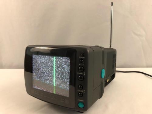
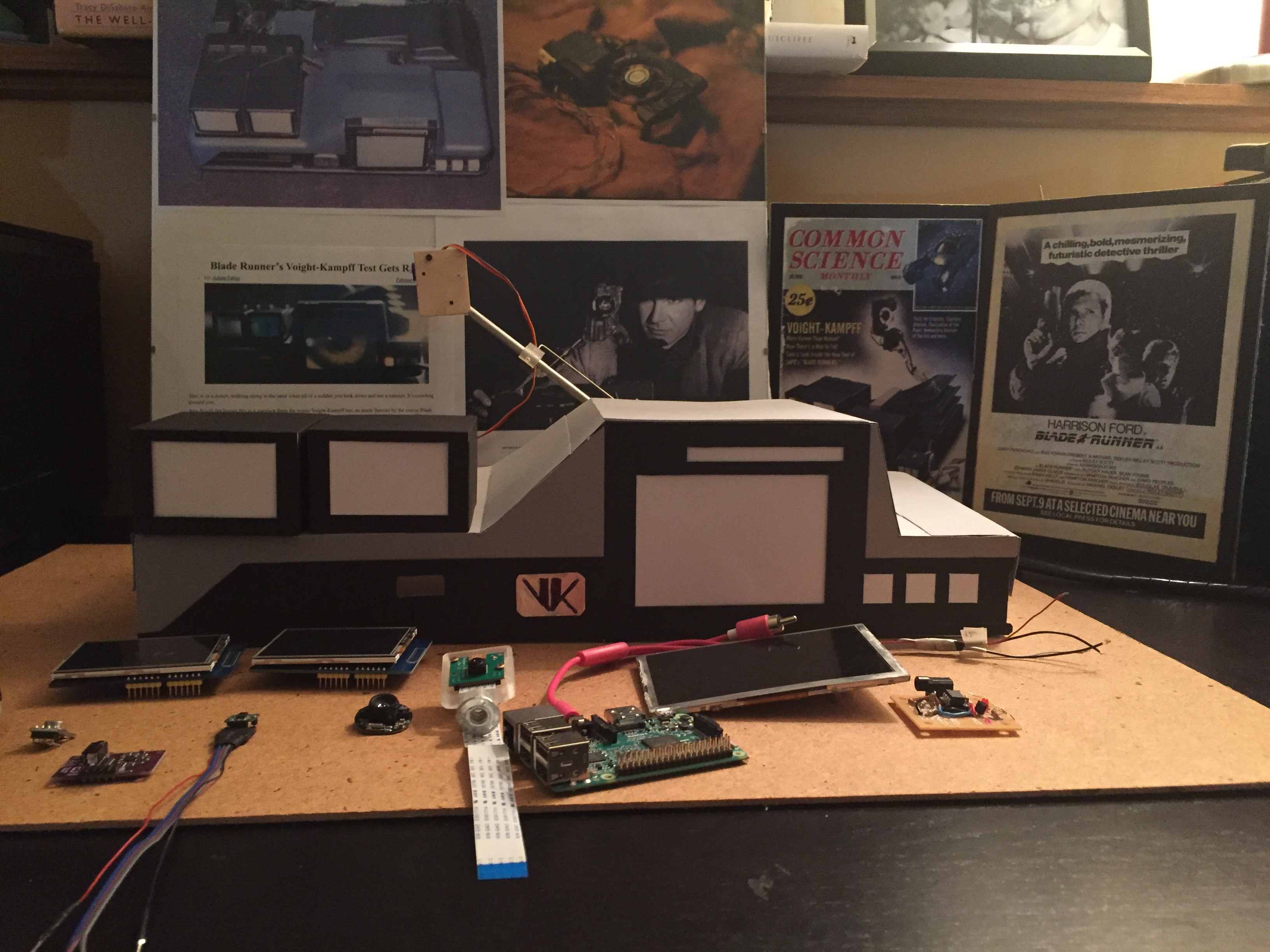
- Voight-Kampff machine (this project) - functional replica of the movie prop
- viEwMotion (View Emotion) - wearable Voight Kampff - which houses the sensors used fort measuring emotional response (in the form of a wrist band).
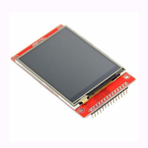
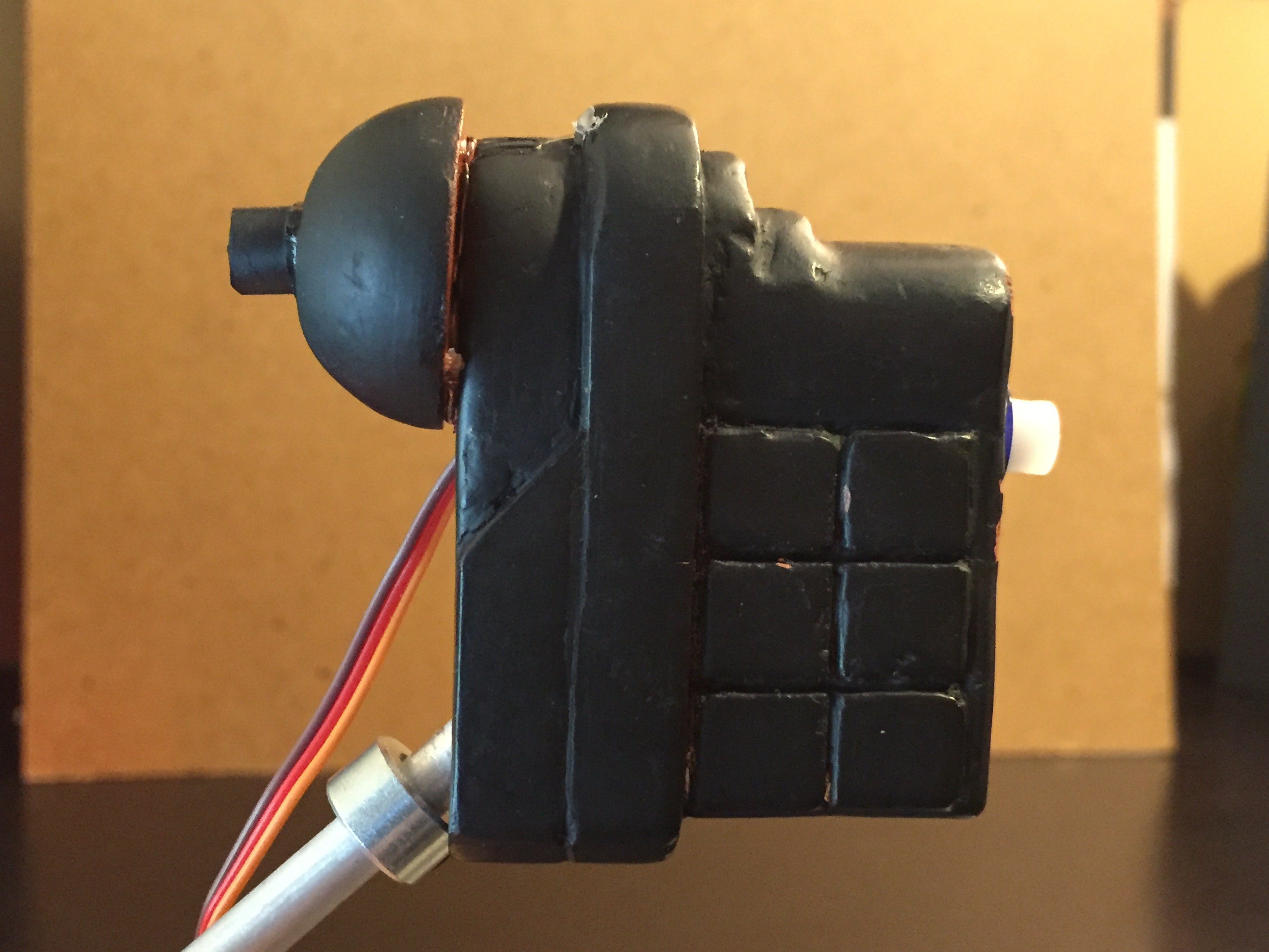
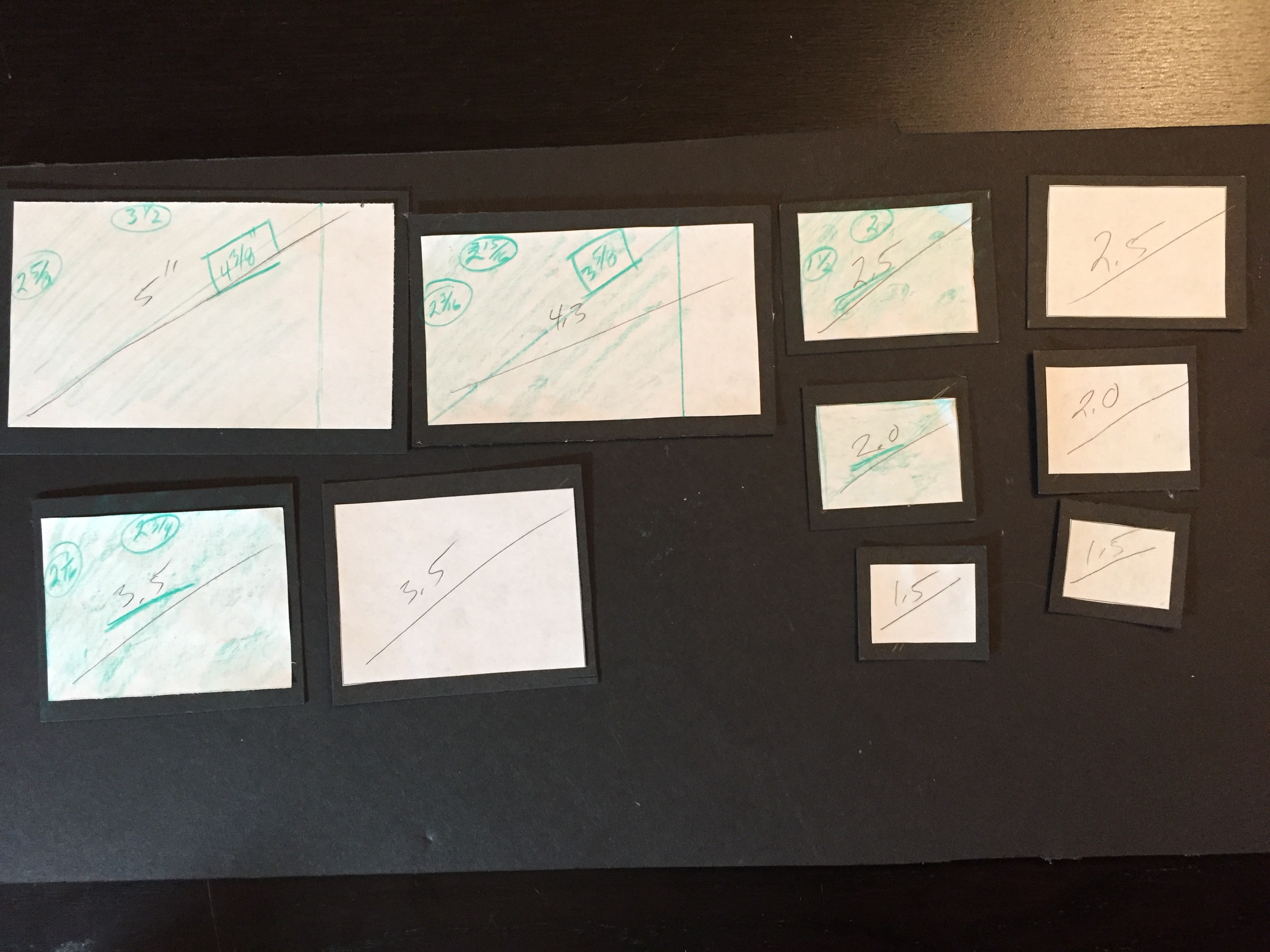
This section of the overall project will address the building and fabrication of the machine used in Bladerunner. This includes working out a complete 3D model of the machine, building the moving parts (arm, "eye", and bellows), interfacing the 3 separate monitors, LED bargraphs, and all software and hardware including schematics.
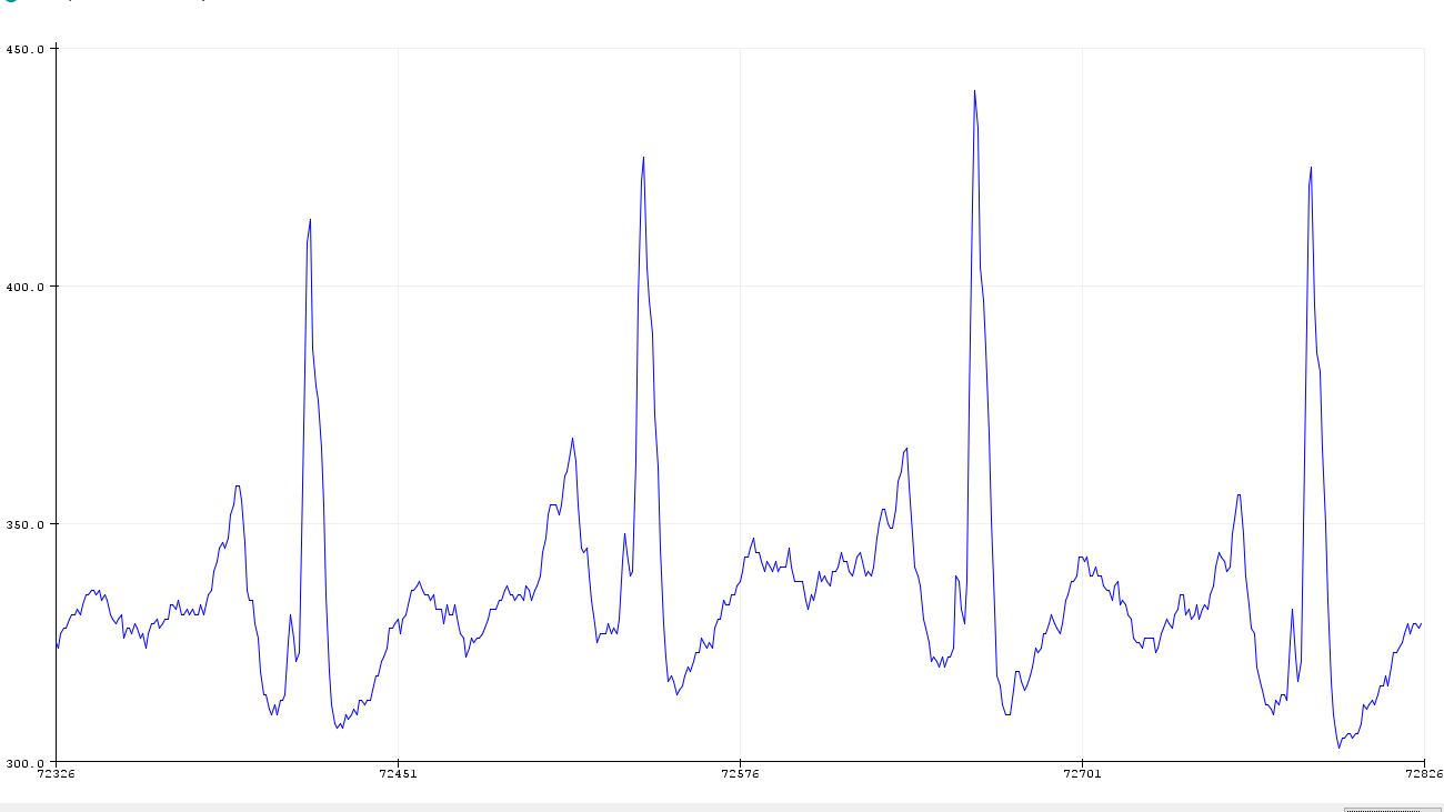
The viEwMotion section will focus on the sensors used (with full schematics, etc.), software algorithm development and fabrication of the wrist band housing the sensors.


 Todd
Todd
 jean.perardel
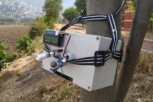
 Guillermo Perez Guillen