 Tom Meehan
I've been trying to get a video of my
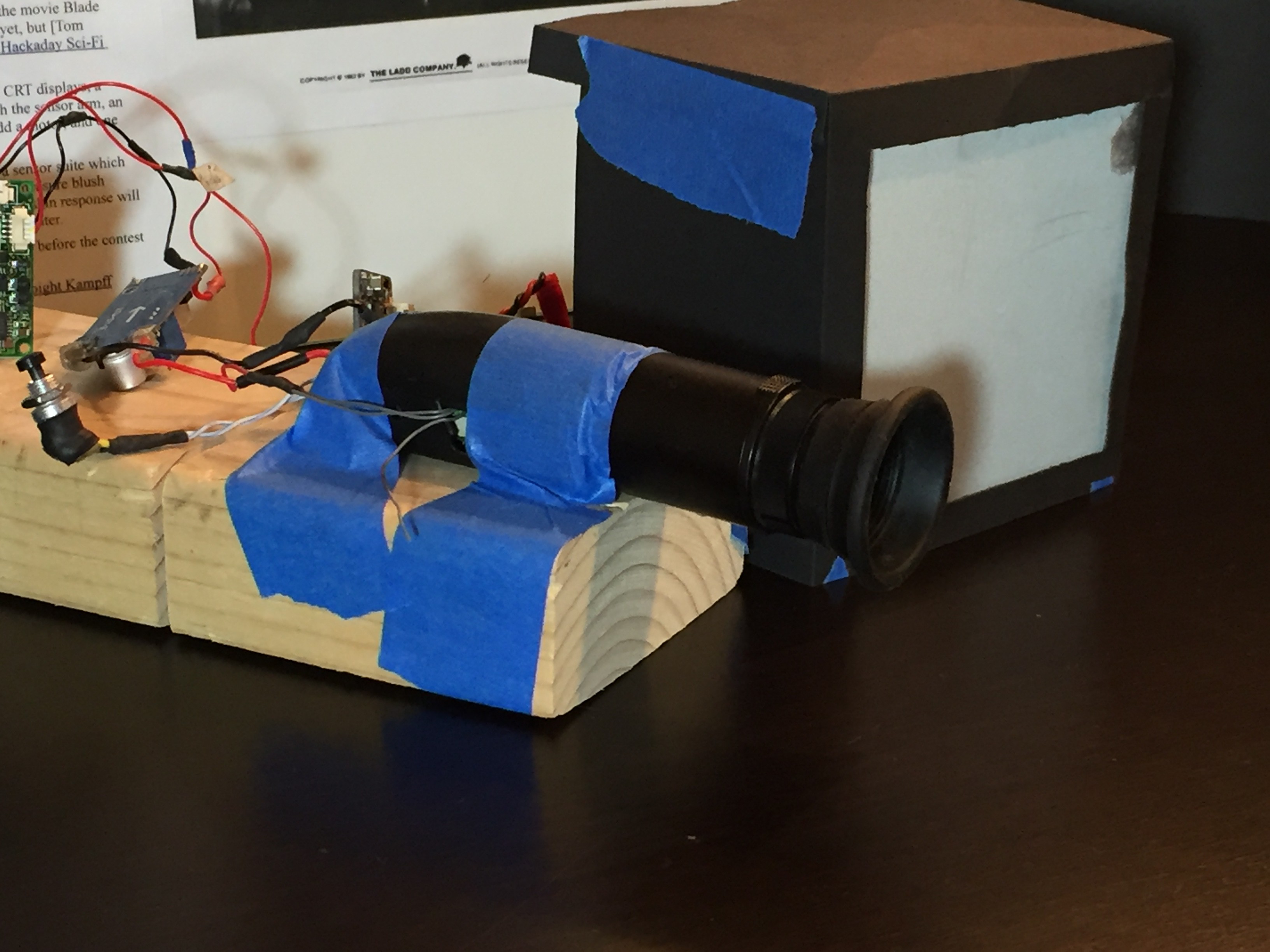
functioning Voight-Kampff “arm” filmed and posted for more than a
week now, finally I recorded it and now I can post it and here it is:
After re-writing my control code
multiple times I finally realized what I was doing wrong – I simply
needed to change my conditional statements from “if” to “while”.
An embarrassing mistake but all to easy to miss when I haven't had
anyone else look at my code (to easy to read “into” your own
writing – if I'd had someone else look at it they would have caught
it immediately – “palm to forehead” moment).
Here's the functioning code:
/*VK arm - lift, extend, rotate
*  Serial communication used in initial debugging
*  Goal - use signal from RPi to trigger the arm raise, extend and
*  rotate sequence
*   - endstops for safety and to signal extension and rotation limits
 */

//Arm Raise motor -Stepper motor driven by Pololu A4988 driver
  int RaiseDir = 8; //dir pin - arduino pin to direction pin on Stepper Driver
  int RaiseStep = 9; //step pin - arduino pin to step pin on Stepper Driver

#include <Servo.h>
//Servo's
// Arm Extension servo
Servo ExtServo;    //Extends and retracts upper arm
  int ExtStop = 3;
  boolean ExtVal = true;
  int ExtFor = 100;  //adjust according to speed and weight
  int ExtBack = 0;
  int ExtHold = 90;
//  "Eye" Rotation servo
Servo RotServo;     //Rotates eye Up (forward) or Down (back)
  int RotStop = 6;
  boolean RotVal = true;
  int RotUp = 100;  //adjust according to speed and weight
  int RotDown = 86;
  int RotHold = 90;

void setup() {
  ExtServo.attach(2);  //470uF electrolytic cap- for motor start
  ExtServo.write(ExtHold);
  RotServo.attach(5);  //470uF electrolytic cap- for motor start
  RotServo.write(RotHold);
  pinMode(RaiseDir, OUTPUT);
  pinMode(RaiseStep, OUTPUT);
  pinMode(ExtStop, INPUT_PULLUP);
  pinMode(RotStop, INPUT_PULLUP);
  Serial.begin(9600);
}

void loop() {
  delay(1000);    //Pause
  Raise();        //Raise the arm
  delay(1000);    //Pause
  Extend();       //Extend the arm
  delay(1000);    //Pause
  Rotate();       //Rotate "Eye" forward
  while(1);
 }

void Raise() {
  Serial.println("Raising Arm...");
  digitalWrite(RaiseDir,LOW); // Set Dir high
    for(int x = 0; x < 125; x++)   {
      digitalWrite(RaiseStep,HIGH); // Output high
      delay(10); // Wait
      digitalWrite(RaiseStep,LOW); // Output low
      delay(10); // Wait
        }
  Serial.println("Arm Raised...");
  return;
}

void Extend() {
  ExtVal=digitalRead(ExtStop);
  while  (ExtVal == true)  {
    //Serial.println("Extending Arm..  ");
    ExtServo.write(ExtFor);
    ExtVal = digitalRead(ExtStop);
    //Serial.print(ExtVal);
  }
   //Serial.println("Arm Extended..");
   ExtServo.write(ExtHold);
   return;
}

void Rotate()  {
   RotVal=digitalRead(RotStop);
   while (RotVal == true) {
    //Serial.println("Rotating Up..");
    RotServo.write(RotUp);
    RotVal = digitalRead(RotStop);
    }
    RotServo.write(RotHold);
   //Serial.println("Eye In Position...");
    return;
}
Well anyway, it's fixed and working
correctly now. I do still need to add a “retract and store”
sequence but that is fairly simple now and will depend on the types
of end-stops I use to detect the positions of the different moving
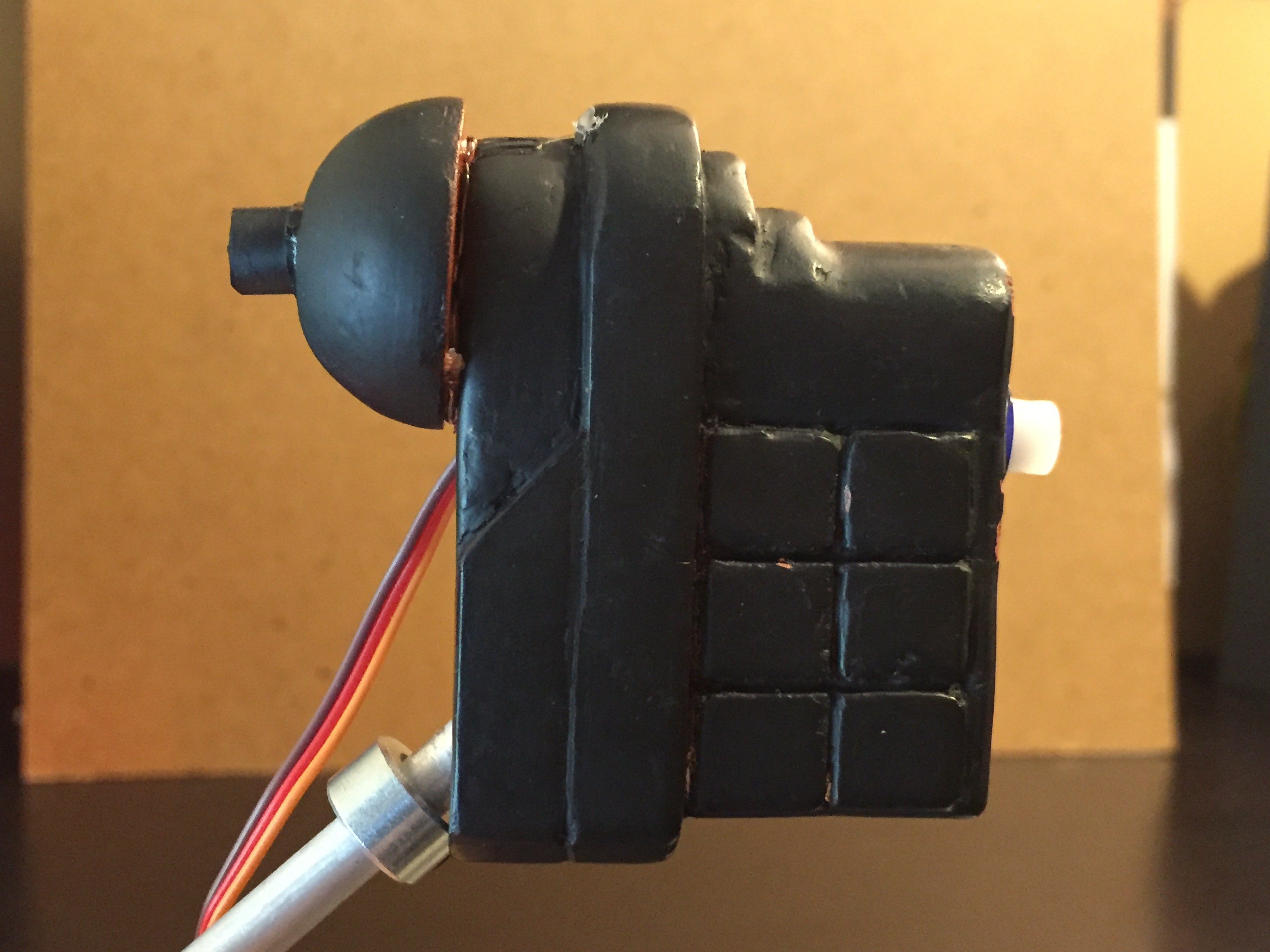
parts.I'm continuing to work on modeling, what I refer to as, the “eye” servo box. I haven't added all the details yet since I'm still trying to finalize the scale (in reference to the “shaver”). One attempt is visible in the current video (3D-printed the front half, filled lines with “Bondo Glazing and Spot Putty”, sanded, primed and painted black).
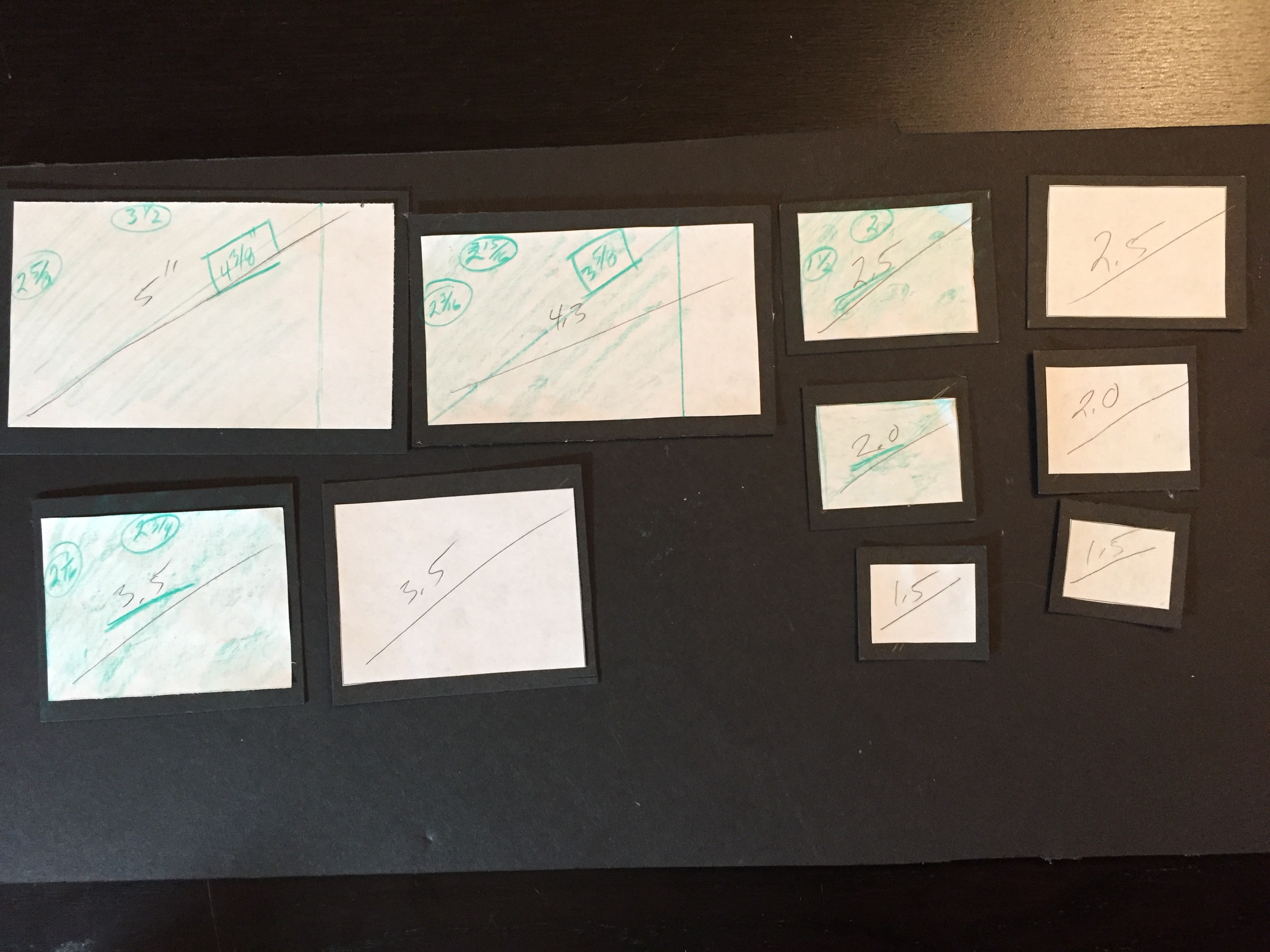
The screens on the VK are continuing to
give me headaches – I made cutouts of the different available LCD
screen sizes (that support “component input” and 4:3 aspect
ratio) just so that I could check out how they might work.
Discussions
Become a Hackaday.io Member
Create an account to leave a comment. Already have an account? Log In.