 Thomas
Hackable DC/DC Converters
A quick search for "LM2596 DC 4.0-40 to 1.3-37V Adjustable Step-Down" on AliExpress presents a range of cheap DC/DC converters with voltmeter from $1.50. I discovered that the voltmeter uses a STM8S003F3P6, the low-cost µC that's the target of my first Hackaday project. The first specimen I hacked didn't have the most promising hardware design: it was necessary to solder patch wires to pins of a 0.65mm TSSOP package *).
The second one I ordered looked like this:
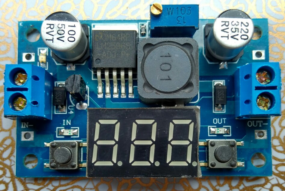
The first obvious thing, already visible on the vendor's pictures, is that the 7S-LED display nicely covers the voltmeter part including all the passive components.
*) Of course, it's still possible to remove the 7S-LED display, and use the pin as a breakout for no less than 11 GPIOs!
Under the Hood
Underneath the LED display we find this nice arrangement:
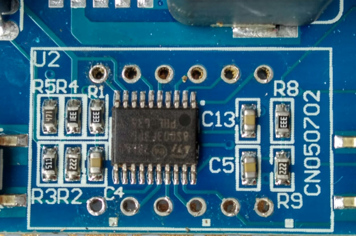
The LM317 in TO92 package is directly connected to the voltage divider R4/R3 (the LM317 lacks the recommended capacitor Cout, Cin is shared with the LM2596). C13 is connected to Vcap (STM8 1.8V core supply circuit). R1/R2-C4 and R8/R9-C5 are the "voltmeter inputs" (PC4 Vin, and PD3 Vout). R5 is connected to the green power LED.
PC3 is connected to LED "in", and PB4 to LED "out" without current limiting resistor (the same as the 7S-LED display). Like in the first variant,
the "design" relies on the limited current driving capability, and on
the surprising robustness of the STM8S outputs. The LED power
dissipation is limited by a 4% duty cycle (there is a small risk of
accelerated aging).
Isn't there anything else missing? Yes, a bypass capacitor for the STM8S003F3P6! A 100nF capacitor should be added to prevent communication errors (see instructions). Any doubts about the robustness of the STM8S are unfounded: it will tolerate circuit bending practices on a mass production scale ;-)
I first assumed that the GPIOs used for the 7S-LED display are the same as in the first variant, but they're not (the STM8S003F3P6 is rotated by 90º).
The LEDs "in" and "out" are now connected to dedicated
GPIOs (which is good for us), but the keys still share a GPIO with LED segments like in a 70s pocket calculator (PC5/SegE and
PD2/SegG). It would have been really easy to use PB5 for reading the
keys but well ...
As mentioned in one of my previous posts there is a thing I learned about the STM8 ICP interface: connecting the NRST pin isn't needed unless SWIM has been disabled in the device configuration, and if the port pin is in input mode at least sometimes. Since PD1/SWIM is connected to pin4 of the display, iIt's possible to get a new firmware onto the µC without removing the 7S-LED display! Programing usually fails on the first attempt but that's OK for our needs: once there is a Forth console we can use IAP (in application programming).
Which variant to buy
I only plan to provide full board support for the variant in the pictures above. Other variants are either more expensive, or they don't have GPIOs on the LED pads that can be re-used easily. If you want to buy a unit, on AliExpress search for "LM2596 DC 4.0-40 to 1.3-37V Adjustable Step-Down" or simply post a comment here. I've seen a green and a blue variant, and both are easy to identify ("CN2596-2" is written on the back, LM317 is in TO92 package, it has only few passive components near the 7S-LED display). The green variant is better, since the ICP pins (NRST & SWIM) are broken out to pads.
Modding Options
The board has some quirks, but we can work around them:
- for reading ADC values, the display should be dark (the anode, and the cathode outputs should be off - due to the required low duty cycle that's no problem
- ADC Vin ADC is easily accessible on the backside of the PCB (after cutting the copper trace it can be used for measuring something else)
- ADC Vout can be used for an output voltage control loop (or, after modification, for measuring the output current)
- PC3 can be exposed by removing LED "in"
- PB4 can be exposed by removing LED "out"
- LM2596 Pin 5 "/ON-OFF" can be cut and connected to PB4 for controlling power out (the LED "out"should be replaced by a pull-up resistor).
- the feedback loop of the LM2596 can be controlled by GPIO PC3 (thanks to @K.C. Lee for proposing a simple solution)
More information is in the project log.
Building a Programmable Power Supply
Using the build instructions, the board can be modified into a programmable power supply.
- a simple lab power supply with control features (scripting, monitoring, synchronization)
- precision temperature control (i.e. not switching-mode but by setting the power)
- motor or a hydraulic valve solenoid control
- LED power supply
- battery charging
- ..
The Wiki on Github shows some examples.
How to get the code
Of course, you can write your own code, e.g. in C, or assembly. I'd like
to invite you to try the tailor-made eForth in the build instructions
instead. You'll find that programming a power supply has never been
easier!
The first stable version of the code is available. Please refer to the GitHub repository, the Releases, and the project logs for up-to-date information!
How to connect the power supply to a PC
The DCDC-Board can be connected to a PC with a TTL serial interface adapter (and optionally to a ST-LINK programming interface at the same time) in the following way:
DCDC-converter .      .----o serial TxD "TTL"
               .      |      (e.g. "CH340 USB serial converter")
               .     ---
               .     / \  1N4148
               .     ---
               .      |
7S-LED pin3/PC3>>-----*----o serial RxD "TTL"
               .
GND ----------->>-----*----o serial GND
               .      |
               .      |
               .      .----o ST-LINK GND
               .
7S-LED pin4/PD1>>----------o ST-LINK SWIM
               .
Please note that the serial interface is shares a GPIO with segment DP of the 7S-LED display (the board-support code takes care of that).