 Thomas
Programmable power supplies are required (and expensive) test equipment in the automotive industry: the price tag for a single test channel can be several $1000 (and sometimes more).
You'll never hear me say that one can fully replace such a piece of equipment on-the-cheap, but it's always possible to use cheap equipment for doing a tests that support the development, and thus to reduce the risk that the stuff you develop won't pass the acceptance test. It's also sufficient for "exploratory testing", a method that's used in addition to verifying requirements (i.e. find out if known requirements are sufficient for higher level goals, like robustness or functional safety).
One of the common power cycle robustness tests for ECUs (automotive Electronic Control Units, e.g. motor control, body controller, brake control) is the cold cranking test. The "test pulse" (i.e. the effect on the power supply) looks like this:
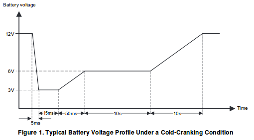
Please note that the time scale in the first part of the function is in the order of miliseconds, and later in the order of seconds! The first part often induces a reset of an ECU (even if the requirements say that it shouldn't). No automotive embedded system I've heard of can operate valves (or other actuators) from 3V, but the 50 ms slope that follows serves to "stress test" ECU diagnostics. The 10s plateau then requires the ECU to rest in a "degraded mode" from which it has to recover somewhere in the 10s slope leading to normal operating conditions. Of course, the test pulse is just an acceptance test. For the automotive supplier, the objective is developing a robust ECU, not to meet the exact requirements.
I'll be using a $2 piece of equipment, a hacked CN2596-2 "DCDC converter with Voltmeter" operating on STM8 eForth.
The pulse can be generated by simply defining the output voltage as a function of time. I took the values from the chart and made a table for the STM8 eForth library word @inter in order to transform time in [ms] to voltage in [mV].
Thanks to the STM8 eForth Background Task creating a test pulse is very simple: all it takes is a task that converts the provided TIM value (ms ticks) with the help of a mapping function to a target voltage:
#require @inter

CREATE cctab
  6 ,
  12000 0 , , 3000 5 , ,
  3000 20 , , 6000 70 , ,
  6000 10070 , ,12000 20070 , ,

: coldcrank ( -- )
  TIM cctab @inter mV ;

' coldcrank BG !
CREATE defines the new word cctab, which returns the address of the following cells. In the following lines, the , take numbers from the data stack, and create a table by storing them in the dictionary memory (i.e. right after the word cctab. The word coldcrank gets the timer ticker value and the address of the table on the stack and uses @inter to get the value corresponding to the value of the 16bit ticker (in ms), and uses mV from the last log entry to set the output voltage. Negative values, and values > 20070 ms result in the saturation value 12000 mV (just like in the diagram). The pulse is thus repeated ever 65.536 s.
On my more than 20 years old damaged scope, the result looks like this:
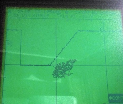
If the picture doesn't show the initial drop in the diagram above. That's because time in the test pulse spec isn't to scale: on this scope a 70ms voltage drop to 3V all but disappears at a time scale of 5s/DIV.
The rising slope looks good (it appears to be linear, so the CN2596 hack works!), and also the two constant voltages (6V and 12V) look good. Discharging capacitors to 3V in just 5ms won't work without additional effort (with a 330R load the output voltage drops to 5V after 60 ms from where it rises to the plateau of 6V in about 20ms). Please keep in mind that this result was reached with a quick hack - it took longer to write this log, than to make this application work!
These guys from FIG were right, Forth is very effective, especially for building test equipment. For decades I only used C and assembly for embedded programming, and I had missed out on a very good tool.
EDIT: for discharging the output capacitor of the CN2596-2 board (220µF) from 12V to 3V in 5ms about 22R load is required. If the DuT (device under test = the test load) has a power rating of more than about 6.5W@12V that would always be the case. If the power rating is lower it depends: if the DuT has an ideal 3,17W DC/DC converter the 5ms slope in the test pulse spec could be met, too. Of course, most DC/DC converters are far from ideal, and a 22R/10W resistor with a generous heat sink can be added for safety.
EDIT: the example code now works with STM8 eForth 2.2.23 (#require for e4thcom, FILE/HAND removed).
Discussions
Become a Hackaday.io Member
Create an account to leave a comment. Already have an account? Log In.