 Thomas
The CN2596-2 board keys (labeled "IN" and "OUT") are now supported.
I removed the LED "IN" from the word OUT!. With the B4-controls-LM2596-ONOFF mod, the DCDC converter can be switched on and off easily.
I'll describe the next steps in an update to this log entry later on. The code in TG9541/STM8EF develop branch is up-to-date.
EDIT: the development branch now contains ready-to-use DCDC code (i.e. with timer initialization, and the pwm output word).
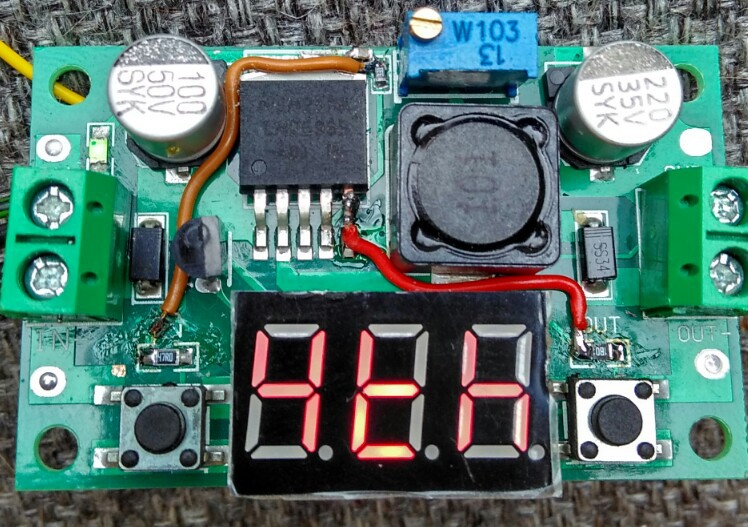
I also added ON/OFF control for the LM2596 through port PB4 (former LED "OUT"). The led got replaced by a 1.8k 0804 resistor as a pull-up, pin5 of the LM2596 was cut in the middle, and connected to PB4 (red wire).
 The following code toggles the LM2596 output voltage on and off when pressing the "IN" key:
: b ?key if 65 = if out @ 1 + out! then then ;
' b bg !
A little explanation for C programmers: in Forth most of the dataflow happens on the data stack (it's maybe easier to understand for JavaScript programmers: the blank between Forth words is a bit like the . between jQuery filter words, and the stack corresponds to the $ object).
": b" defines word b. ?key puts "<key code>" and "-1" " on the stack if a key is pressed, and "0" otherwise. if takes a number from the stack, and goes to the next then if the value is "0". Inside the condition structure, = tests if the key code equals 65 and in the next if the value of the outputs register out is incremented to toggle bit0, and then written to PB4 with out!. Note that 65 is of course the ASCII code of "A" (key "OUT" corresponds to "B", and both keys pressed together is "C").
The operator ' (tick) put the address of b on the data stack. which is assigned to the background task vector BG with the store operator !. From there on b gets executed in the background in a 5 ms interval.
The while the code above runs in the background, the output voltage can be changed on the console interactively:
\ set maximum voltage (e.g. 12V, use trimmer to adjust)
0 pwm
\ set low output voltage (about 0.5 V)
450 pwm
As you may have guessed, \ is the comment operator for single line comments. pwm pops a value from the stack and sets the TIM1_CC3 compare register (the duty cycle of PC3 controls the ground level of the LM2596 feedback loop). Since the board init routine sets the Timer1 reload register to 1000, the compare value 450 corresponds to 45.0% duty cycle.
Discussions
Become a Hackaday.io Member
Create an account to leave a comment. Already have an account? Log In.