terryspitz
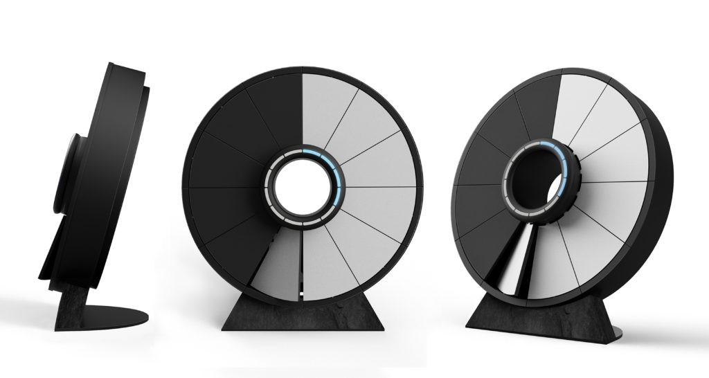
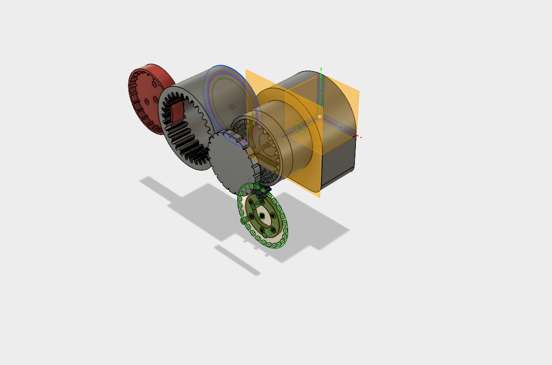
There's so much good stuff in this project! Dreaming up a cool look in glass, chrome, mirrors, gears. 3d design software. 3d printing prototypes. Designing and building a circuit. Programming an embedded controller to keep time.
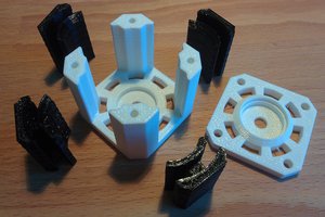
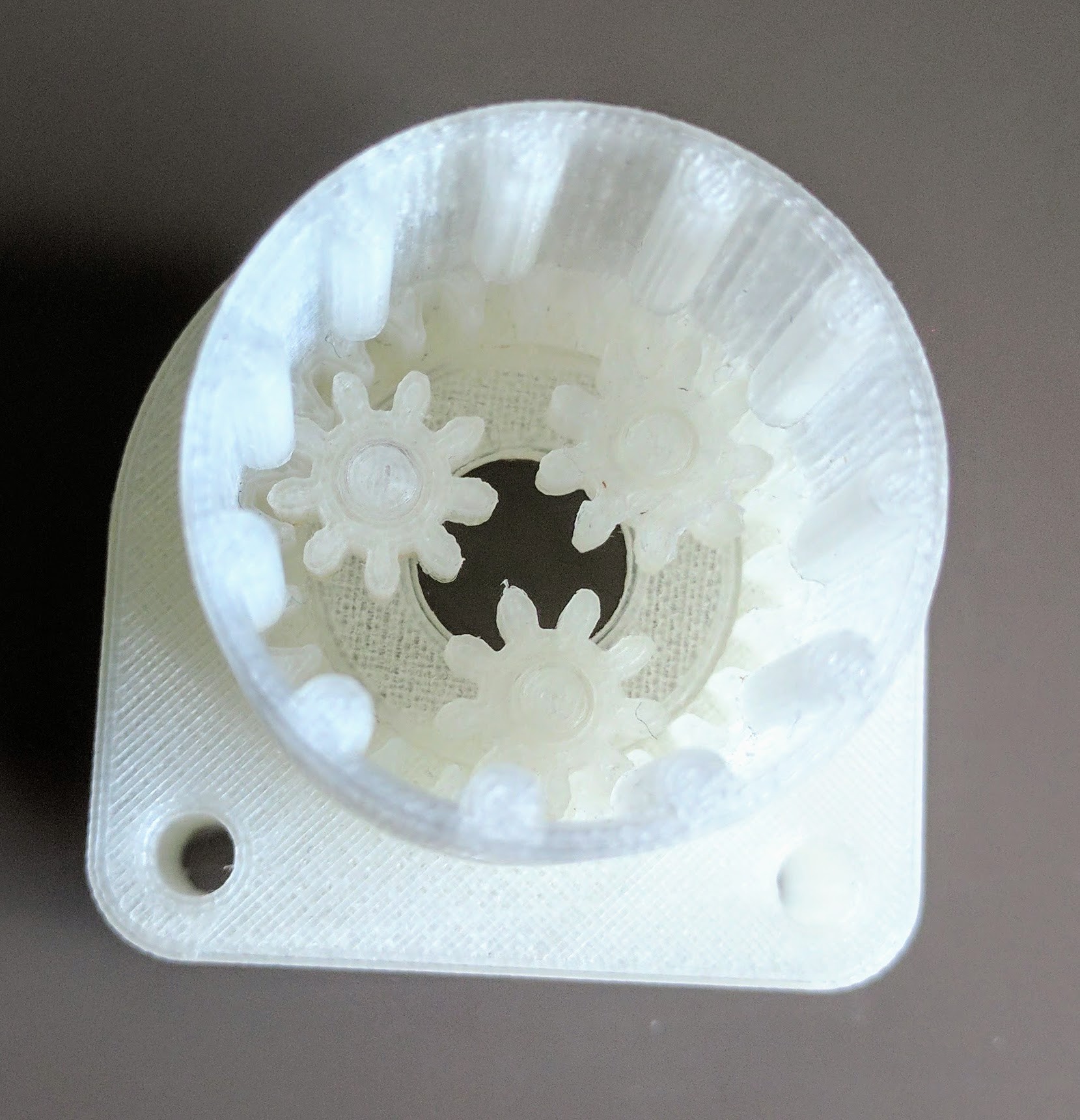
Prototype 1 was designed to be easy to 3d print. It's nearly made : not entirely successfully but with some good learnings. The motor came geared 240:1 but with 3V input that still made the rollers rotate at 1 or 2 revs per second which is too fast to drive the discs via friction (and unnecessarily fast for minute or hour discs). So I need to design my own lower gearing. Enter Wikipedia!
https://en.wikipedia.org/wiki/Cycloidal_drive
And
https://en.wikipedia.org/wiki/Epicyclic_gearing
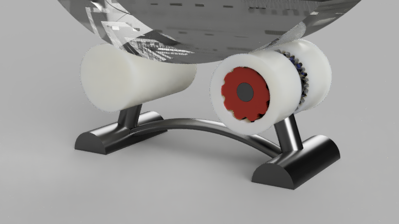
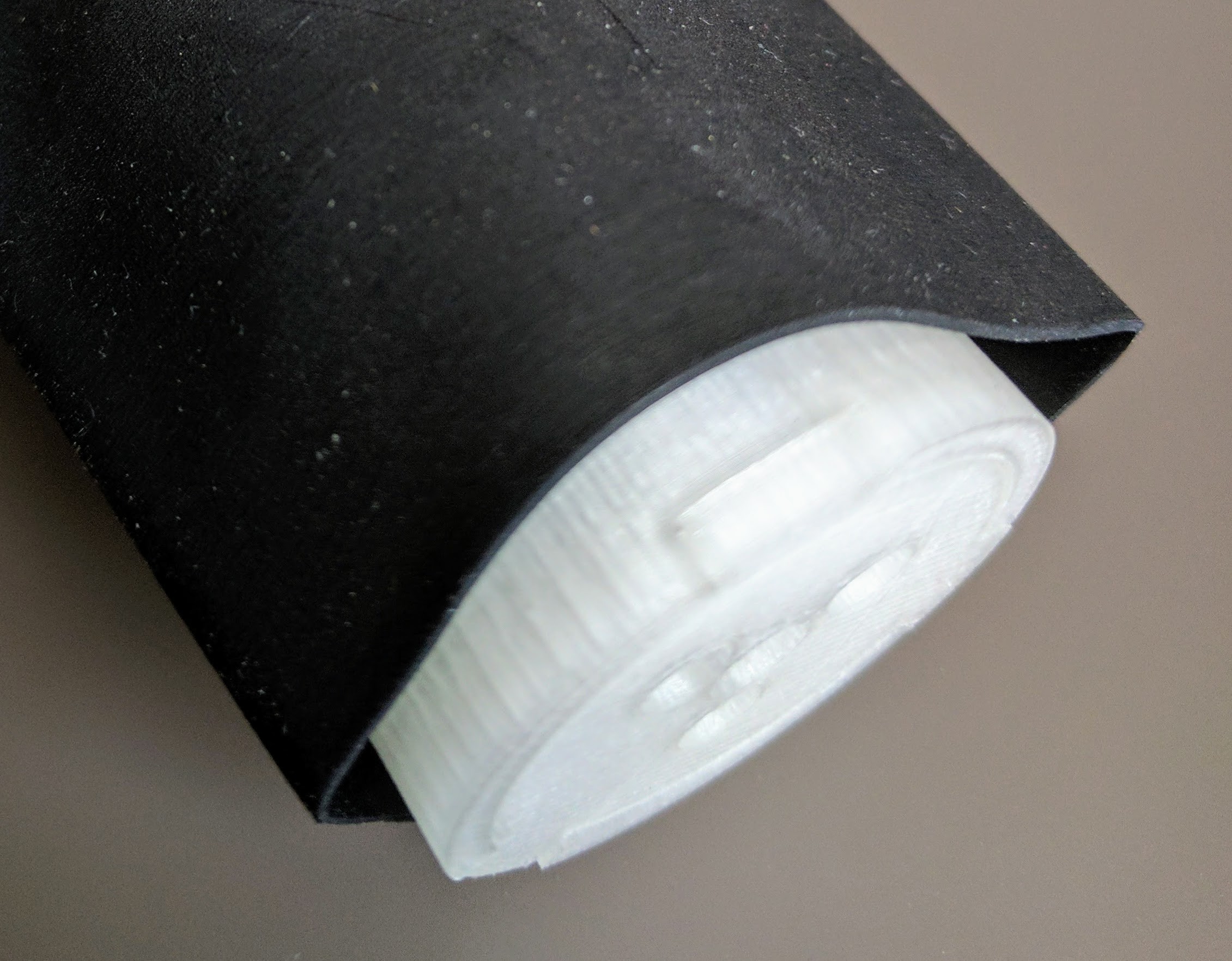
This means larger rollers in prototype 2 which gives me a chance to reduce two motors in the first prototype to one, hide it inside the first roller along with all the gears to drive both disc, and potentially hide the electronics in the second roller.
 Charles Galambos
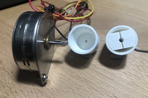
 kmatch98
 Keith Elliott