Introduction
Thermal Imaging technology used to be priced prohibitively outside the budget of hobbyists until recent years. Late 2012 when I started working on my 1st Thermal Imaging project, the lowest cost thermal camera available on the market was the Flir i3 (priced at $995 back then). Moreover, there was (to my knowledge) absolutely no lower cost, open-source alternative solution on the market to these expensive, proprietary devices - that mostly had to do with the high development and manufacturing costs of high/medium performance IR FPAs and lenses and with the timid availability of low cost, low performance IR modules (FPA + lens + ASIC), still not implemented in any low-cost Thermal Imager.
I was therefore highly motivated to explore the possibility of developing a Thermal Imaging platform that was low cost ( < $200 to manufacture) and could offer sufficient performance for some of the less demanding hobbyist level tasks. That's how I've started working on Thermal Imaging devices.
A bit of background
1st attempt: Mechanically Microscanned Thermal Imager (MMTI)
I've started prototyping a device around the MLX90620BAD 16x4 IR array. The idea was to select a low-cost (implicitly low performance) IR FPA that had a low pixel FOV (2.5° x 2.6° FOV / pixel) and a satisfactory NETD (0.08°K at 1 fps in its datasheet; found out the hard way during testing that it was more like 0.4-0.5°K - still have no clue how they got to that figure).
Then, by means of a stepper-motor controlled pan-tilt platform (that had its rotation axes centered as well as possible to the FPA's surface center in order to simplify pixel position calculations) produce a pattern of controlled sub-pixel shifts (microscanning) of the whole IR module.
Each thermal data frame would be sequentially fed via WiFi to a connected iOS device that would form in realtime a composite high resolution image from the individual low-res frames (in the end a 176 x 44 final high resolution image would be obtained out of 121 frames of 16x4).
The prototype consisted of:
- Melexis MLX90620BAD 16x4 IR array
- PIC32MX795F512L based USB Starter Kit II + Starter Kit I/O Expansion Board
- MRF24WG0MA Wi-Fi G PICtail Daughter Board
- 3-axis stepper control board based on 3 x A3977SED (self designed / manufactured board that I had lying around since my early 20's) - naturally, only 2 axis used
- Vexta PK246PA stepper motors that I had lying around (1.8° / step - had to use 1/8 micro stepping to obtain 0.225° steps to fulfill my sub-pixel shifting resolution demands)
- 3S 1600mAh LiPo battery
- cheap laser module (from a laser pointer) - to evaluate microscanning pattern accuracy and orientation
- custom pan-tilt platform (self designed / CNC manufactured) - to allow precise centering of MLX90620BAD FPA surface center to the pan-tilt platform rotation axes
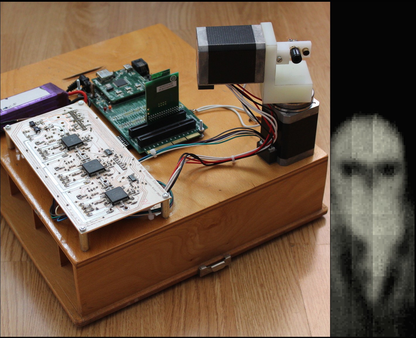
Here's an image of what the Hardware Prototype of MMTI looked like and to the right is the high-res composite image 176 x 44 (formed out of 121 frames of 16x4) - 'self portrait' - yes, I stood frozen for 121 seconds :)
Conclusions drawn from the MMTI prototype testing:
- Successfully verified the validity of the microscanning concept of this particular setup - I was actually surprised by the rather good alignment of pixels and frames
- Sufficient spatial resolution
- Much higher NETD than expected (specified 0.08°K at 1 fps in MLX90620BAD datasheet; found out the hard way during testing that it was more like 0.4-0.5°K - still have no clue how they got to that figure)
- High pixel non-uniformity (although all MLX90620 are factory calibrated to a certain degree of non-uniformity); I had to implement a pre-scan calibration to get to satisfactory uniformity
- High measurement noise for MLX90620BAD (as sensor frame rate is increased, the noise increase too, rendering any frame rate higher than 4 FPS useless for this application)
- Concluded that the primary performance...
 Marius Popescu



 Samuel Wantman
 Ashwin K Whitchurch
 Andras F
 jan.marcinowski
Could also use some auto-image-stitching software for larger images.