 Marius Popescu
After countless frustrating hours spent trying to optimize my hardware / software implementation (of the Manchester Encoding scheme that the Hijack project proposed and that I've previously used in the TJ Gen0 prototype) in order to be able to increase the communication frequency (therefore data bandwidth), I've convinced myself I've hit a decisive hardware limitation.
Long story short:
The D6T-1616L sensor that I'm using on the TJ Gen1 prototype produces ~12366 bps of data ( (16 x 16 pixels + 1) x ~12bits x 4FPS)) that TJ has to relay to the iOS device through the microphone input.
To send that amount of data (without using thermal data compression, which I've decided would be the last resort), I'd need to increase the frequency at which the Manchester modulated data is sent through the mic. input from 8820 Hz to something like 14700 Hz or 16000 Hz (divisor of 44100 Hz or 48000 Hz sampling rate).
Put short, sparing you of details, neither of those frequencies worked not even with minimal reliability in spite of my efforts of accurately deriving the sampling clocking from the output sine wave used for power harvesting and using that to clock my output signal.
Bottom line is that Manchester encoding could only take me this far... :)
Then, an "AHA moment" struck me... There's already a 5bit DAC in the micro controller I've chosen for the design, why not try to use a form of PAM (Pulse Amplitude Modulation) ???
This would allow me to keep the communication frequency low and still multiply the data bandwidth: WIN WIN :)
After another few days of painstaking testing I've arrived to a compromise between comm. frequency and different amplitude levels that seems to work best:
- 5 pairs of voltage levels (coding 2bits; 1 pair is for sync) clocked at 8000 Hz
Let's take a look at the following example:
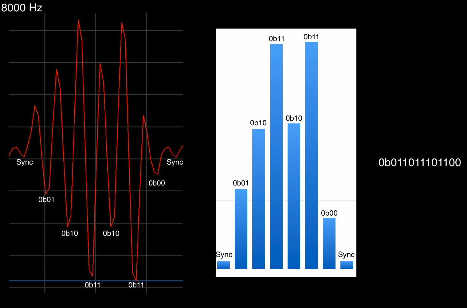
The red test signal was captured (with a super-useful app. called SignalScope Pro) by the iOS device on the mic. input.
The encoding scheme is as following:
- there are '7 blocks' per data packet (1 sync block, 6 data blocks), so each data packet is delimited by a start and an end sync block
- on each block the positive and negative parts are driven identically in absolute amplitude (forming pairs) - this is to assure transitions on every bit (to pass AC coupling on mic. input) and because only the falling edge is measurable (the rising edge is completely useless for measurement because that's where the transition between different voltage levels happens) - see the rising edge on the transition from 0b11 to 0b00
- there are 5 different voltage pairs (symbols), expressed in 5bit DAC input value (where 0 is 0V and 31 is 3.0V):
- SYNC symbol (HS = 16, LS = 15)
- '0' symbol (H0 = 18, L0 = 13)
- '1' symbol (H1 = 21, L1 = 10)
- '2' symbol (H2 = 25, L2 = 6)
- '3' symbol (H3 = 31, L3 = 0)
- The SYNC symbol encodes the sync blocks
- The '0', '1', '2' and '3' symbols encode the data blocks (each block is a 2bit value)
- 12bit values are encoded in 7-block data packets ( SYNC block, 2-bit data block 1, 2-bit data block 2, ... , 2-bit data block 6)
Decoding is done as following:
- The difference in amplitude on each falling edge of the signal is measured by the iOS app. (the bar graph on the right shows the differences measured on the left signal)
- The differences are decoded to symbols by certain thresholds that separate them (raw thresholds are hard-coded in source code but on each thermal data frame (4 times per second) there's a special data packet that the app uses to finely calibrate the thresholds; the differences are really stable over time but there seem to be variations from an iOS device model to another (e.g. iPad 3 to iPhone 5s)
- The detected symbols are transformed to a 12-bit value (by simply merging the 2-bit pairs) that represents the thermal measurement data of a pixel
The modulation scheme is currently used in the TJ Gen1 prototype and works 'flawlessly' (less than 1 corrupt data packet in >100000 data packets...) !!!
It allows me a maximum practical data throughput of ~13714 bps, more than sufficient to send the ~12366 bps that the D6T-1616L produces.
More details on the TJ Gen1 prototype will be published towards the 20th of August :)
Discussions
Become a Hackaday.io Member
Create an account to leave a comment. Already have an account? Log In.