If the video display and CPU are to share the same RAM, then some way is needed for them to concurrently access it. The video data has to be written out to the screen on a fixed schedule as that pixel will be expected by the display at the correct instant. The CPU can wait for data to be read or written - there is no hard deadline.
The RAM has only a single read/write port and can only do one thing at once and takes a fixed amount of time to do this.
One way to allow the video to not operate on such a fixed schedule is to use a FIFO - the video data is read out of the RAM "whenever possible" into the FIFO. The FIFO then has data extracted from it on a fixed clock whenever a pixel is needed. If data is not added to the FIFO in time then there will be an underrun and the image data will have a temporary corruption.
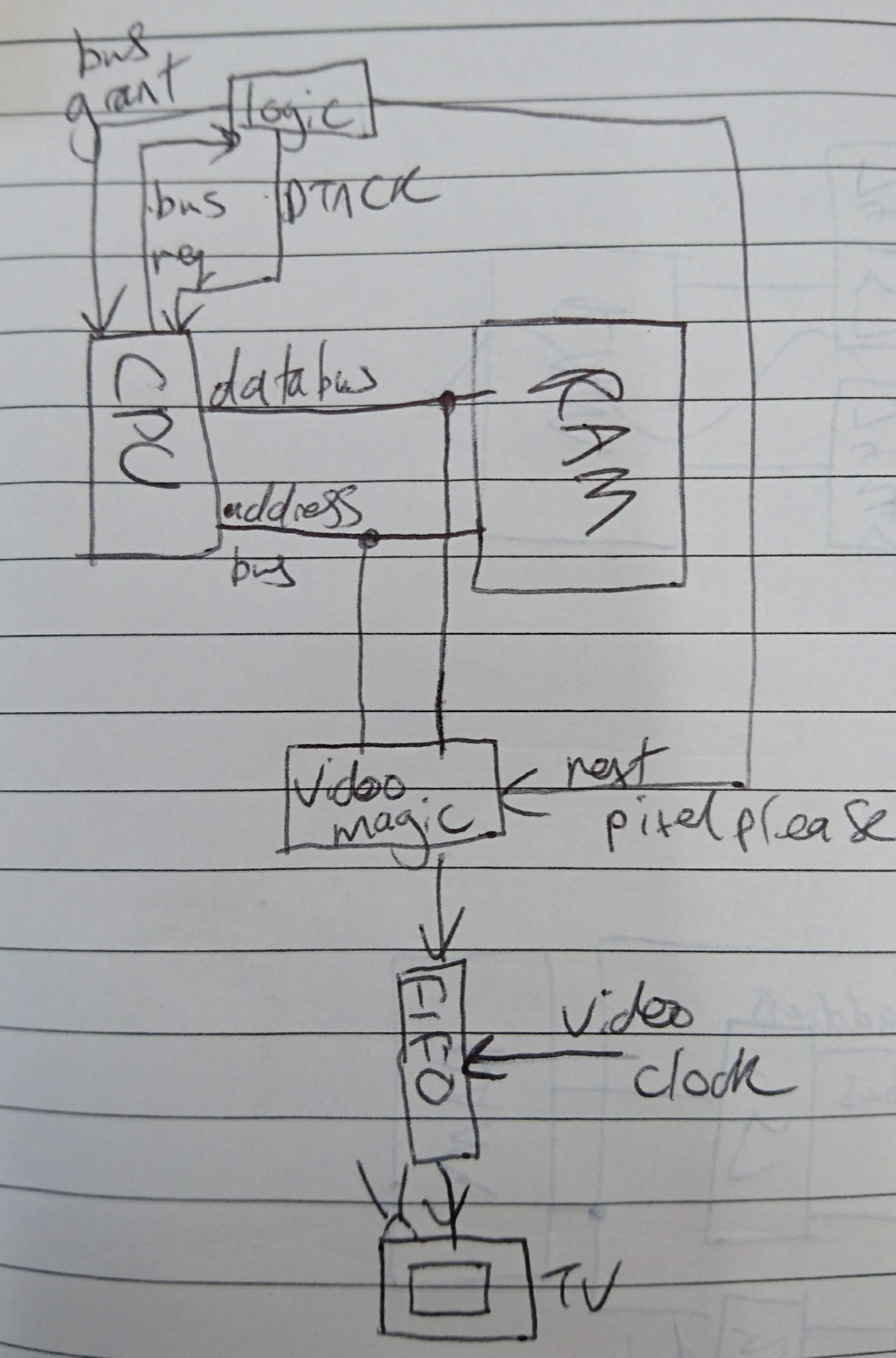
If we get the CPU to relinquish the bus and go to high-impedance whenever we need data, then we can read out a pixel and add it to the FIFO.
The CPU provides a mechanism to arbitrate for the data and address busses via the "bus grant" and "bus request" pins. This takes a certain amount of clock cycles though and gives an unpredictable latency depending on what instruction the CPU is performing. It does require the FIFO though, but doesn't require other circuitry to lock out the bus (as the CPU is doing the high-Z for you).
In retrospect I wish I had looked a bit more into this idea - it's not the way I went in the end.
The route that I chose instead was to not use a FIFO and allow video to be directly scanned out from the RAM at the exact time required. This then meant using a lock on the bus and delaying DTACK until the lock was lifted and the CPU's data dealt with.
There are two elements to this lock: the data bus and the address bus.
The data bus
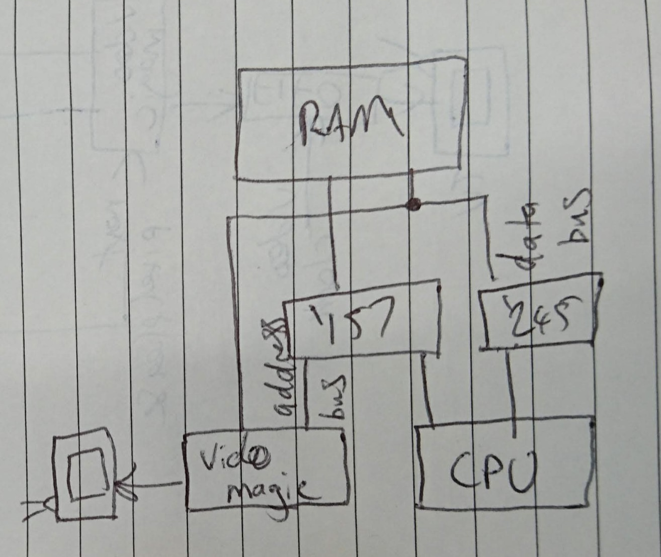
If you consider the data bus, the CPU both reads and writes data to the RAM. The video hardware only reads from the RAM.
If we use a 74'245 octal bus transceiver between the CPU's data bus and the RAM's data bus, we can use it's high-Z feature to disable the CPU's data at any point. If the CPU is driving the bus (ie it wants to write to memory) we can simply disable it via the '245's "output enable" (OE) pin.
This allows the video hardware to access the RAM at any time. Just deassert the OE pin on the '245.
When the CPU is granted access to the data bus the OE pin is asserted and 'direction' (DIR) is controlled with the CPU's R/W pin. If it wants to read from the RAM DIR is set such that the signal is driven from the RAM side to the CPU side. If it wants to write the signal is driven from the CPU side to the RAM side.
A single '245 controls eight bits at a time. Our 68008 has an eight-bit data bus so we only need one. Happy days. The video hardware only ever reads, so no additional hardware is needed - it is connected directly to the RAM's data bus and only latches data when we want it to (so if it 'sees' CPU data there's no worry).
The address bus
Both the mystery video hardware and CPU both drive the address bus in order to select which byte they wish to access (and they will both do it at the same time). So depending on which has precedence, we need to pass just one of these addresses (and the corresponding read/write signal) to the RAM. We will do this with a 2-to-1 multiplexer. Given two inputs we will select one of them to be the output, based on some other signal.
The RAM is 512 kB wide - 19 bits - and these '157s select four bits at a time so we will need five of them. That leaves a pin free to also pass through our read/write signal.
Those '157s will then use a common signal from the control logic to either select the address from the CPU (and its R/W pin) or the address from the video hardware (and its fixed 'read' signal).
The logic
The logic within the system will need to select the video hardware on a fixed timer, and then choose to lock out the data bus, to switch the address bus and finally to control DTACK.
A key part of the "video hardware" is just a binary counter which holds the address (in bytes) of the active region of the screen. As this increments it points to a different pixel/group of pixels within the framebuffer, stored in the RAM. Every time the video hardware is selected by the control logic, the counters count up by one.
Discussions
Become a Hackaday.io Member
Create an account to leave a comment. Already have an account? Log In.