This project started with me seeing an MC 68000 on a breadboard blinking an LED. It seems this is a rite of passage for 68k builds. Although a little bit of a challenge at the time, it's a great way of getting to know your way around the physical package of your CPU. It's also a great way to check the chip and your power supply work. That LED and your stopwatch are your only debugging info!
It really is worth reading the manual rather than blindly copying a circuit off the 'net - I've provided mine to be consistent. Each site has a slight variation (especially for reset) and it's important to know what you are wiring up and why.
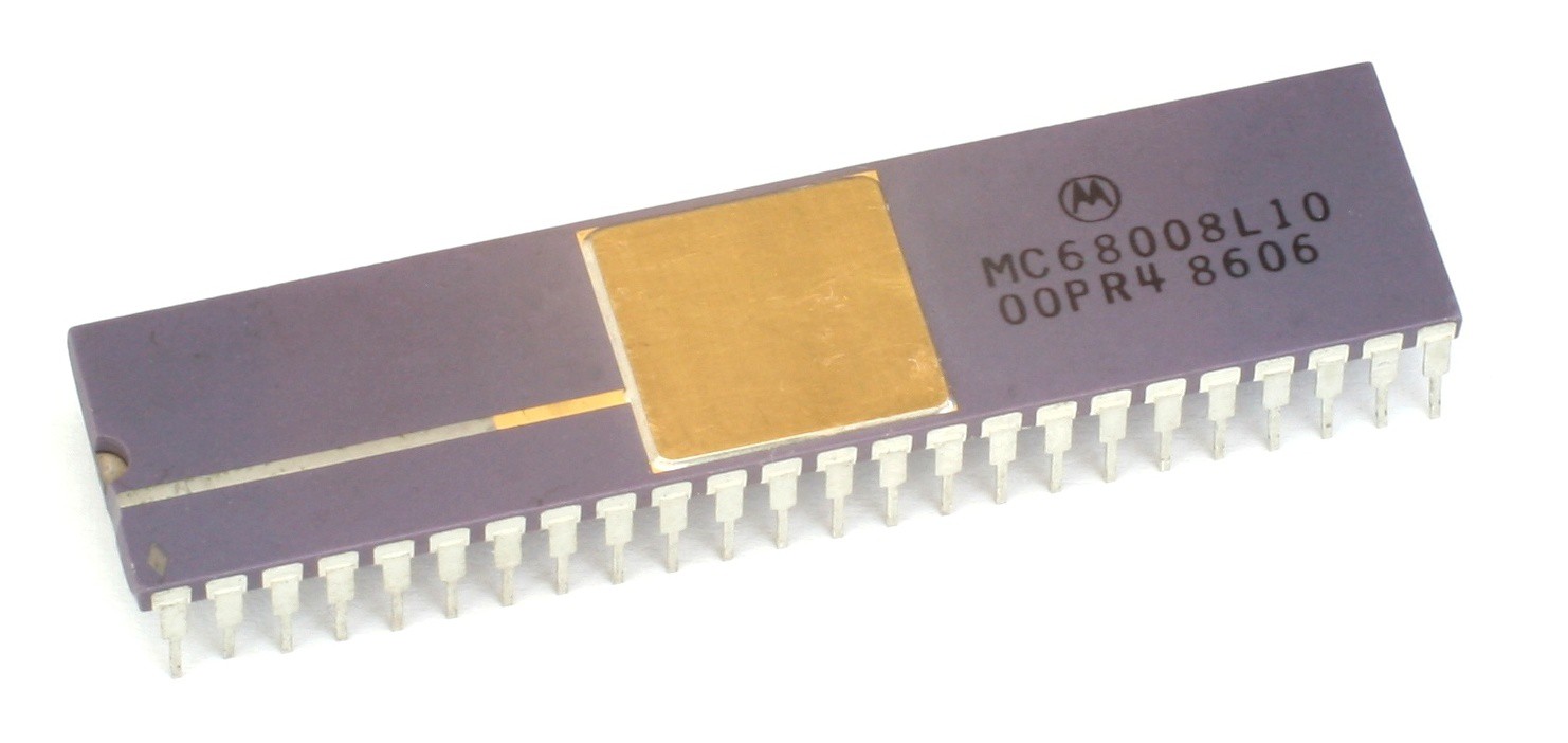 (By Konstantin Lanzet (with permission) - CPU collection Konstantin Lanzet, CC BY-SA 3.0, https://commons.wikimedia.org/w/index.php?curid=4774280)
The CPU provides both input and output signals, and some which can go both ways. Unlike a modern SoC, there is very little on-chip. You've got to connect everything to it yourself which makes things fun. The main signals include,
- 20 bits worth of address bus (output)
- 8 bits worth of data bus (bidirectional)
- a mixture of in/out bus control signals for operating this bus
- a mixture of peripheral control signals for legacy and more generic peripherals
- interrupt triggering signals (input)
- reset, halt signals (bidirectional)
This is the 68008, the cut-down cheaper version of the 68000. The price nowadays is not important (I bought my CPU for £2 on ebay) but the most important difference is that the '008 has an 8-bit data bus rather than 16-bit. It also has 20 bits of address rather than 24. This limits the address space to 1 MB rather than 16 MB. For system designers these narrower busses mean less wires needed, making smaller, simpler and cheaper boards. Depending on the memory ICs you source, you need half as many too.
Moving to 8-bit also pretty much halves the performance, but that's something for later!
Back to free-running. This means allowing the CPU to run, without actually doing anything meaningful. What we're going to do is connect the whole data bus to ground and connect the bus control, peripheral and interrupt signals to say "everything is cool - keep running".
Data pins are active high. What this means is: when a data pin is connected to ground it is interpreted as a logical zero. When it is pulled high it is a one. By connecting the whole data bus to zero we get a eight bits of zero.
Both instructions and data are read over this data bus, with the address bus signalling which address to be read from its address space. We're going to ignore the address bus and always provide eight bits of zero regardless of which address is requested (the the bus control signals will be forced to say 'success' after every request).
Ignoring something special which happens when the CPU is powered on, when instruction fetch begins it will receive zero bytes. Four zero bytes is translated as ORI.B #0, D0. This is the non-GNU assembly syntax, so the destination is on the right. It means logically OR zero with the lower byte of data register zero and store the result there too. The next four bytes will also read 0,0,0,0 and decode the same way. In fact the whole address space will decode to the same instruction.
This means that when the CPU runs it will just walk through the whole address space running OR instructions and moving to the next one! When the program counter hits the top of the address space at 0xffffc it will wrap back round to 0x0 for the next instruction. This will continue forever - this is the free-running system.
Here's how we connect our CPU.
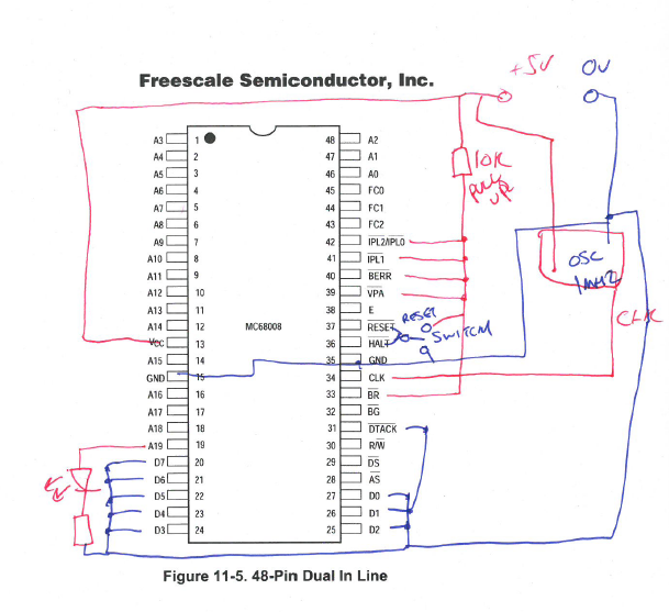 Notable connections
- D0-D7 are pulled to ground - giving zeros on read on our data bus
- A0-A18 is left unconnected, with A19 connected to an LED
- /DTACK - which is active low - is pulled low. This acknowledges the success of our data transfer.
- we have a 1 MHz crystal oscillator connected to our CPU's clock input.
- we have some way of resetting the CPU on initial power on
And here it is wired up!
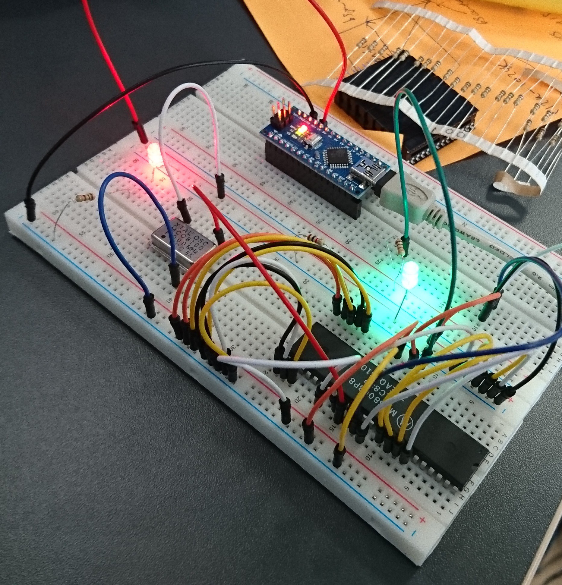
The green LED is our A19 signal. The red LED is showing the board is powered.
How fast does the green LED flash?
The CPU clock is 1 MHz. Each cycle is 1 us. Each bus cycle is four clock cycles. Consulting the manual, a bytewise immediate OR with a data register destination takes four read cycles - that's 16 cycles for the OR. 16 us. We can therefore run 1000000/16 = 62500 instructions per second.
The address space is 1 MB in size and each instruction is four bytes. So that's 262144 instructions. We'll go round the address space in 4.2 seconds, which means the LED will turn on for 2.1 seconds then off for 2.1 and then on for 2.2 for ever more...
Change the clock speed or pick a different address bus pin for the LED and it'll flash a bit faster! The journey has begun...
Discussions
Become a Hackaday.io Member
Create an account to leave a comment. Already have an account? Log In.