 jeromekelty
Beauty is in the details...
The brass details took a lot of time to make but I think they really made for nice accents on the finished piece.
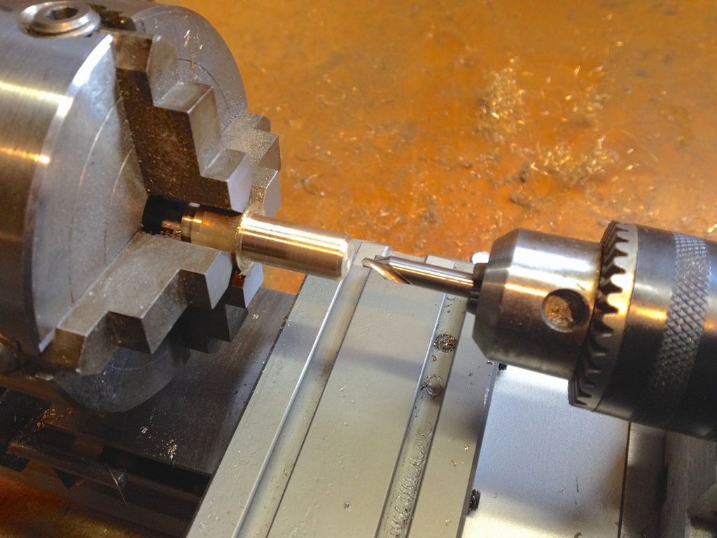
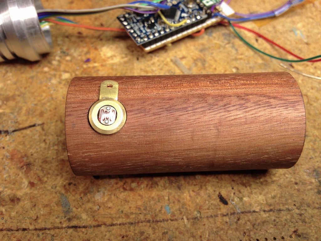
I began with the holder for the 10mm blue LED that sits in the nose piece. This was turned on the lathe and the LED was glued in place with superglue. The holder for the 5mm white LED at the back end was also turned from brass stock and a groove was cut so an o-ring could be fitted so it could be removed- I did this in anticipation of fitting a charging jack at the end of the screwdriver.
Next came the brass holder for the photocell. The photocell has an flat oval shape so the center was bored and then an oval slot was milled in the piece using a 3/16" end mill. After test fitting the photocell a 3/8" diameter relief was cut in the wood body using a 3/8" end mill in my drill press so the photocell holder would sit flush on the wood body.
Once I was happy with the fit I made a mounting tab for the brass photocell body. A small tab was cut, shaped and then annealed with a torch- this makes the metal soft so it's easy to bend to match the curvature of the wood body. This tab was then silver soldered to the photocell holder using a torch.
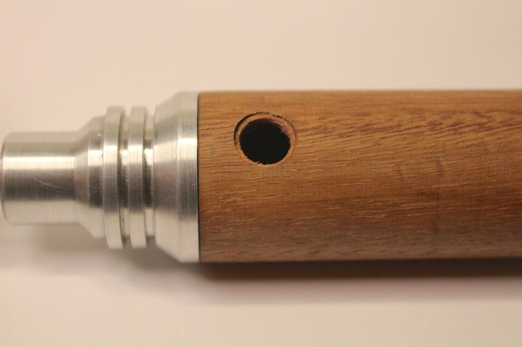
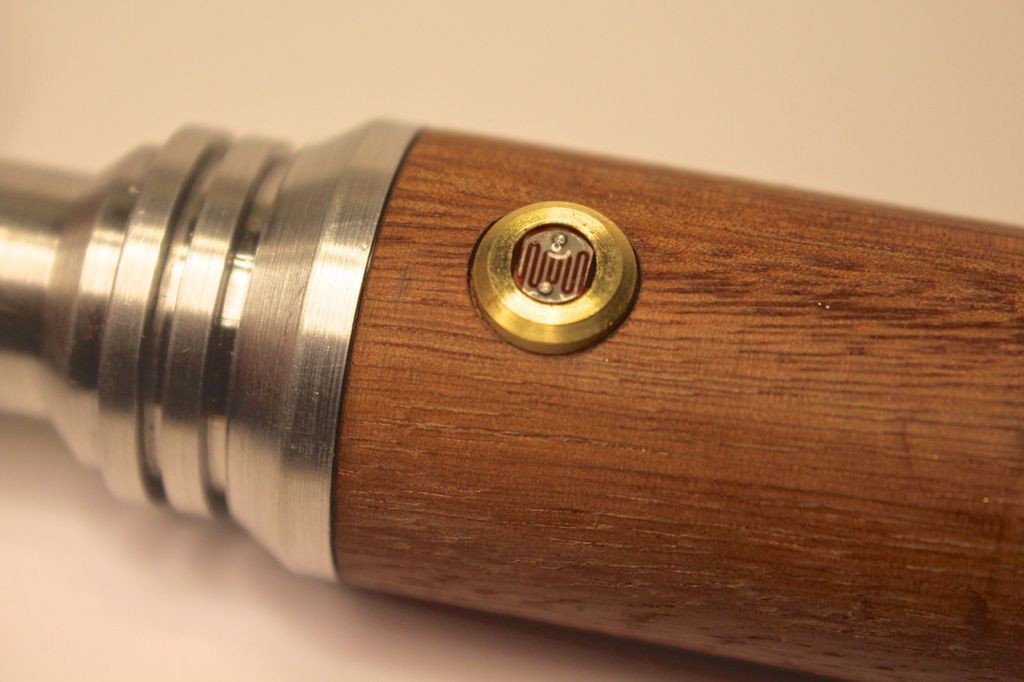
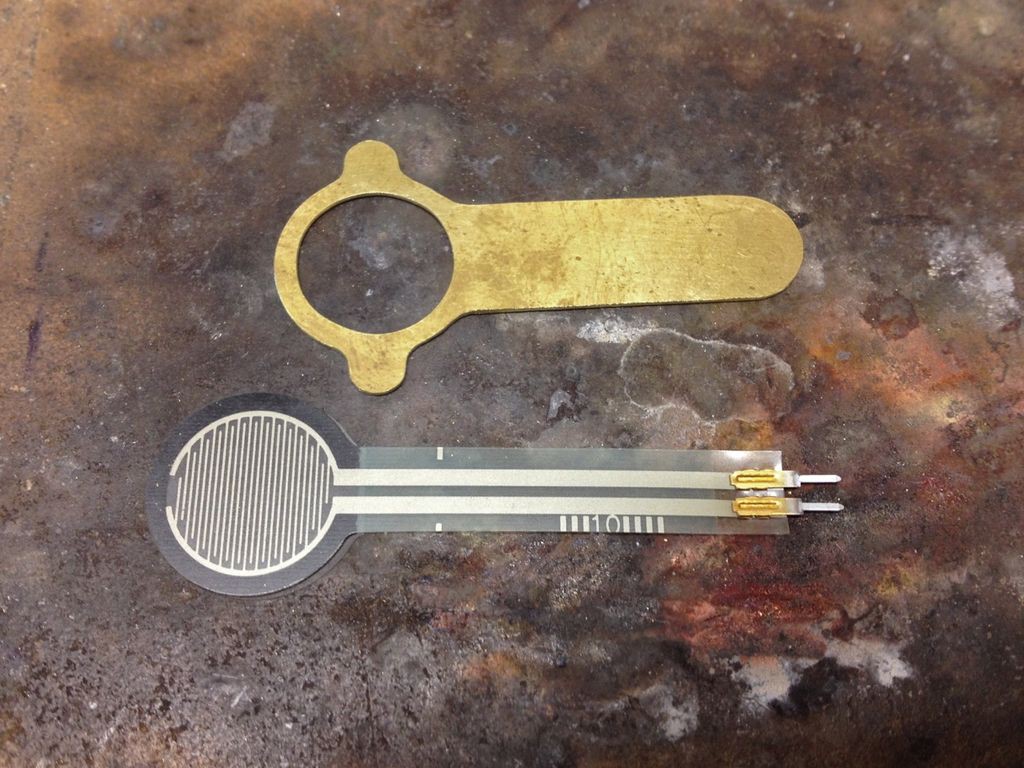
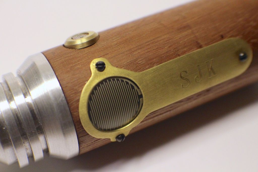
The cover plate for the force sensitive resistor was cut from brass sheet, annealed with a torch and bent to match the wood body. The resistor has an adhesive backing but I figured there was no way it would properly adhere to the round wood body so the cover plate was devised as a way to hold the resistor in place while leaving the proper exposed round pad area. The ends of the force sensitive resistor slide through a small slot cut in the wood body underneath the cover plate- this makes it easy to attach the resistor to the electronics inside the wood body.
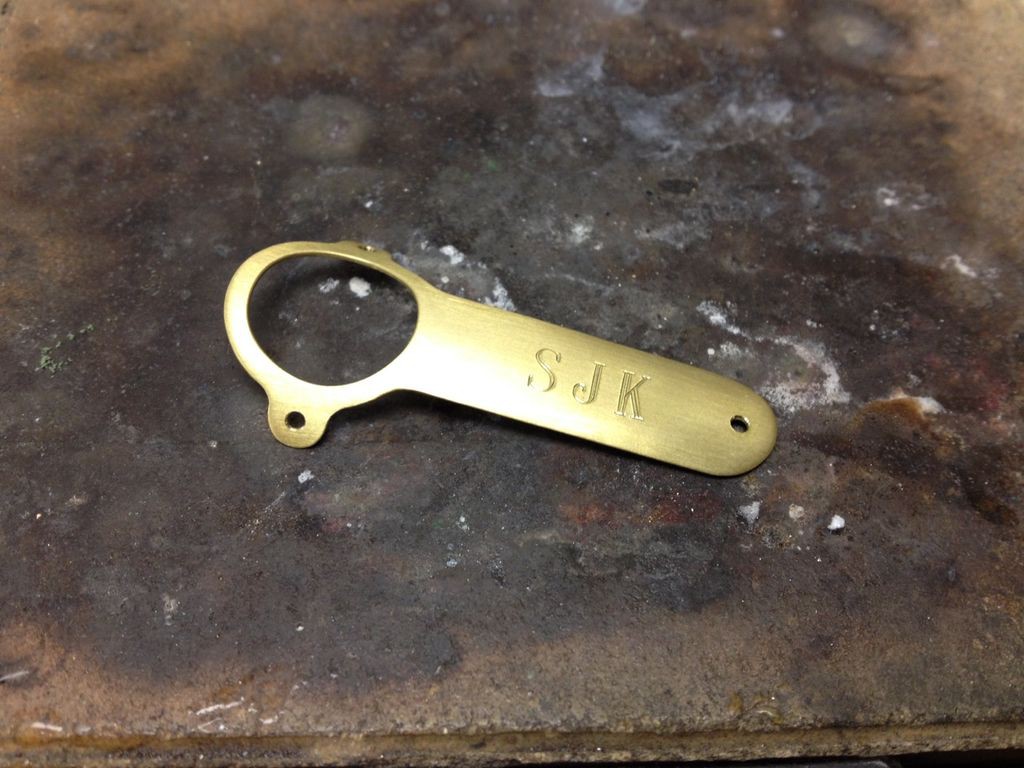
As a finishing touch I engraved my son's initials in the cover plate using an old pantograph engraving machine at my work. Another option that would be neat would be to hand engrave or chemically etch Gallifreyen symbols on the cover plate.
After the cover plate and photocell holder were finished I attached them to the wood body using very small wood screws.
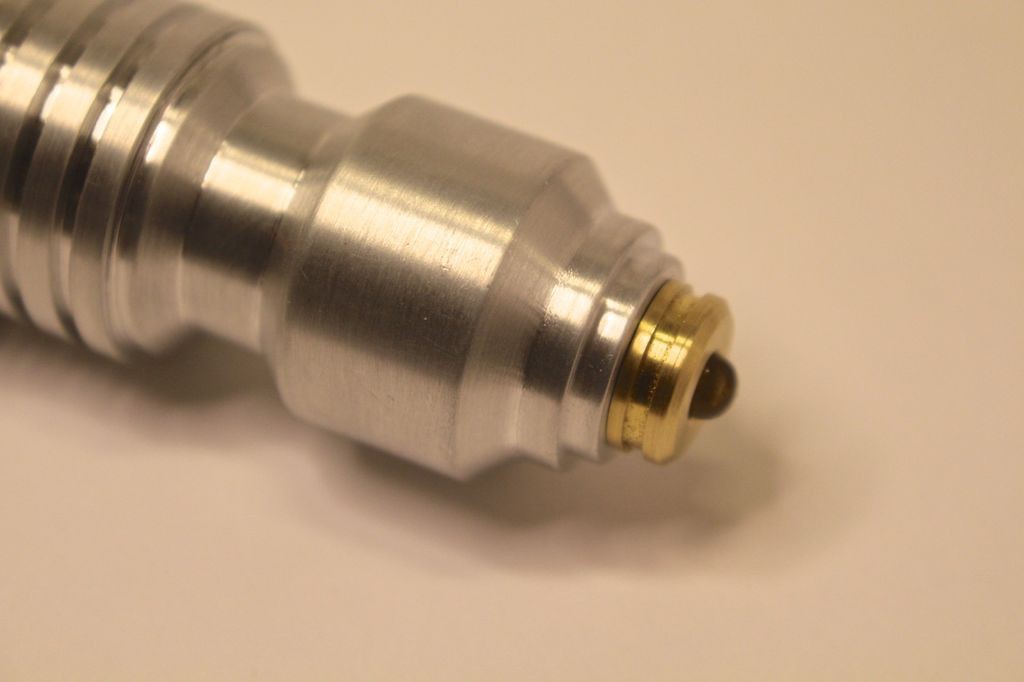
Here's the brass cap that holds the 10mm blue LED.
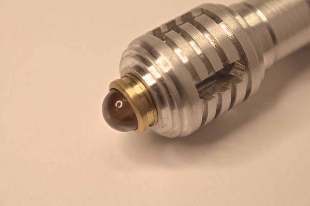
The back of the LED had to be trimmed slightly with a Dremel tool so it didn't extend beyond the diameter of the brass cap.
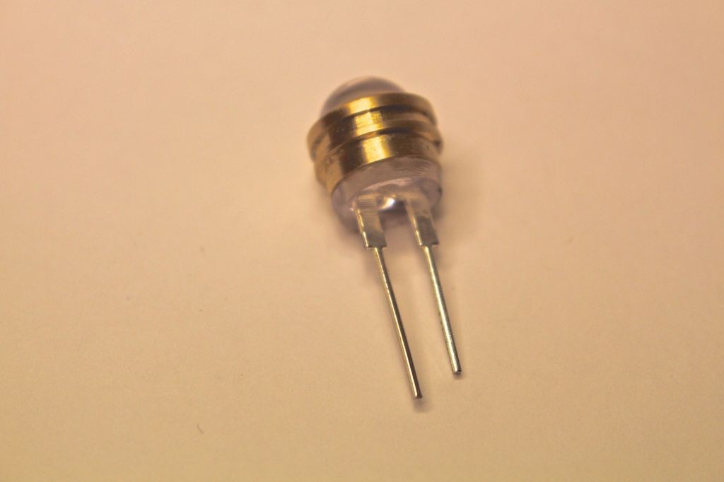
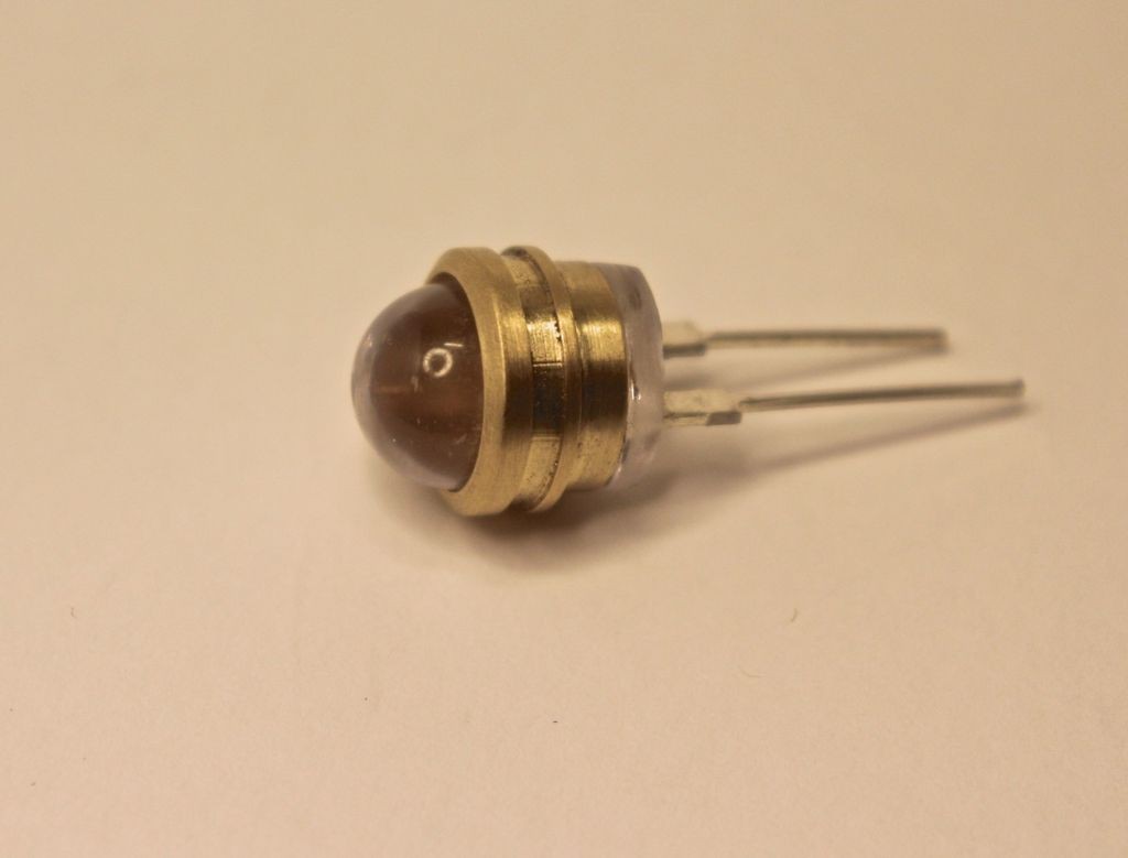
The brass cap that holds the 5mm white LED.
The O-ring sits in a groove and allows the brass cap to be easily removed from the Aluminum end piece. I made this in anticipation of having a charging port (which didn't work out- more on that later.)
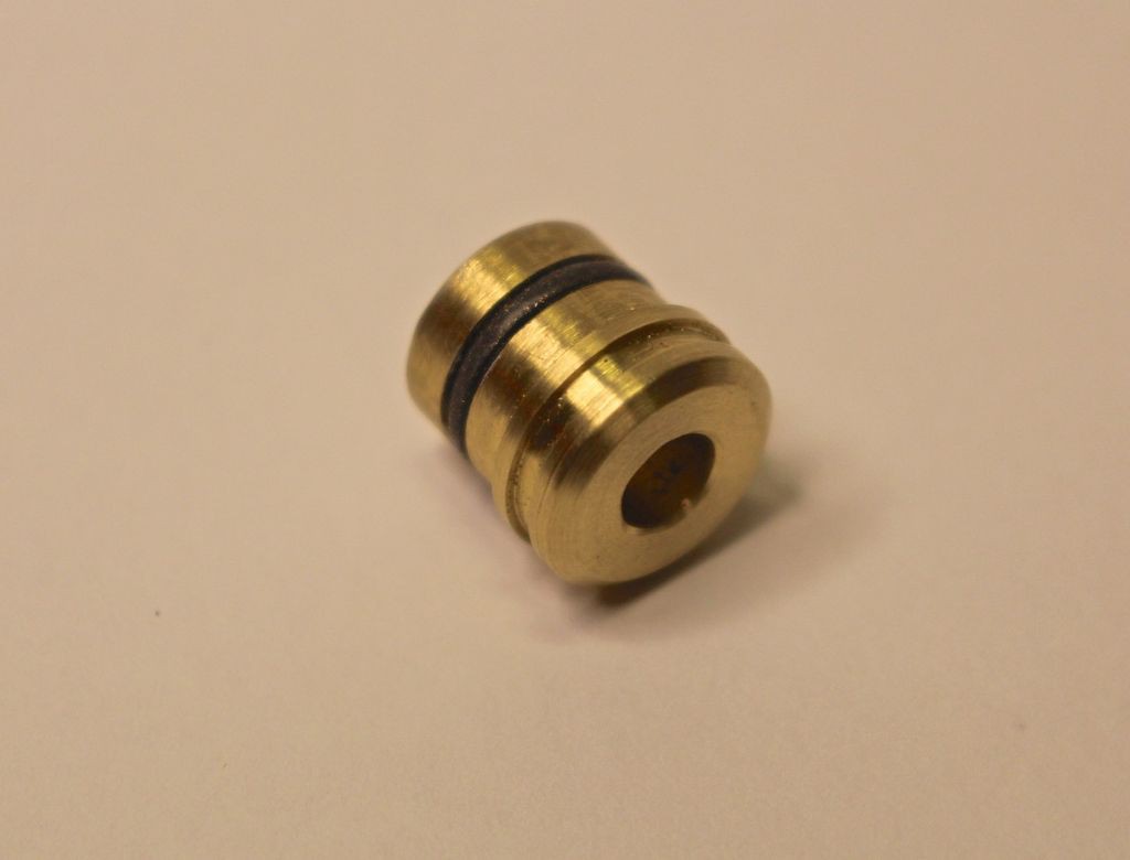
The LED is superglued into the brass cap.

Making a brass holder for the photocell. Using a center drill to mark the location for drilling the hole for the photocell.
Milling the oval slot in the brass photocell holder.


Testing the fit of the photocell.

A relief was cut in the wood body for the photocell holder. This was done with a flat bottom 3/8" end mill.
Test fitting the photocell holder in the wood body. Perfect!
Annealing brass to make it easier to bend. This is for a mounting tab for the photocell holder.
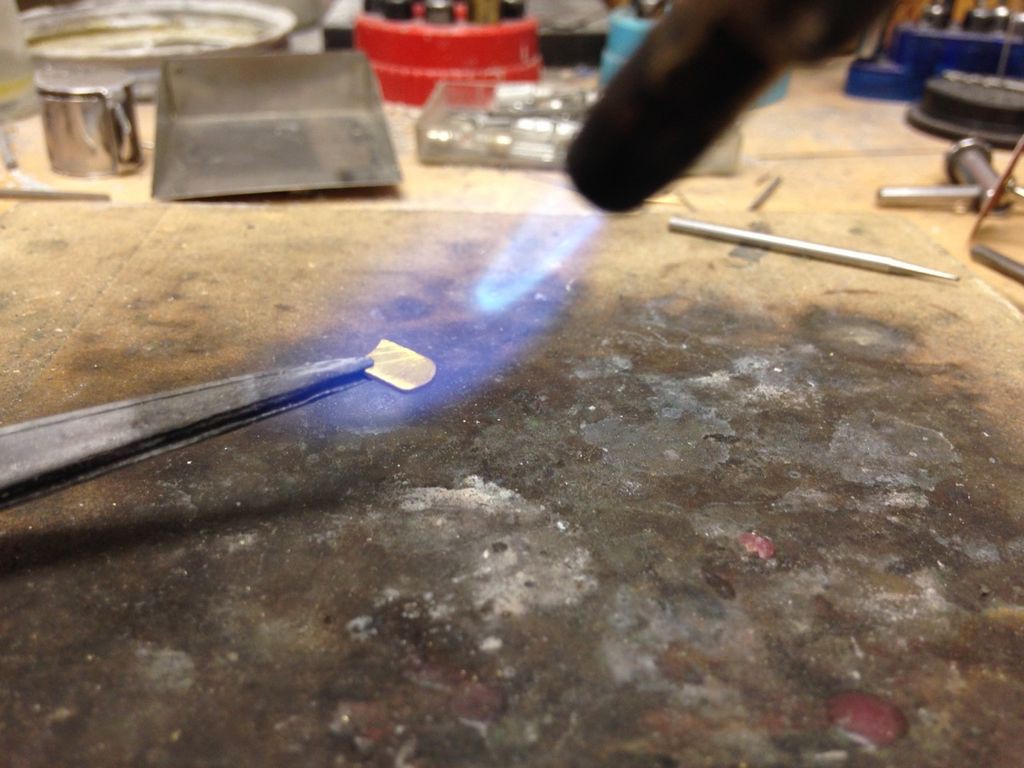
Soldering the mounting tab to the photocell holder with silver solder.
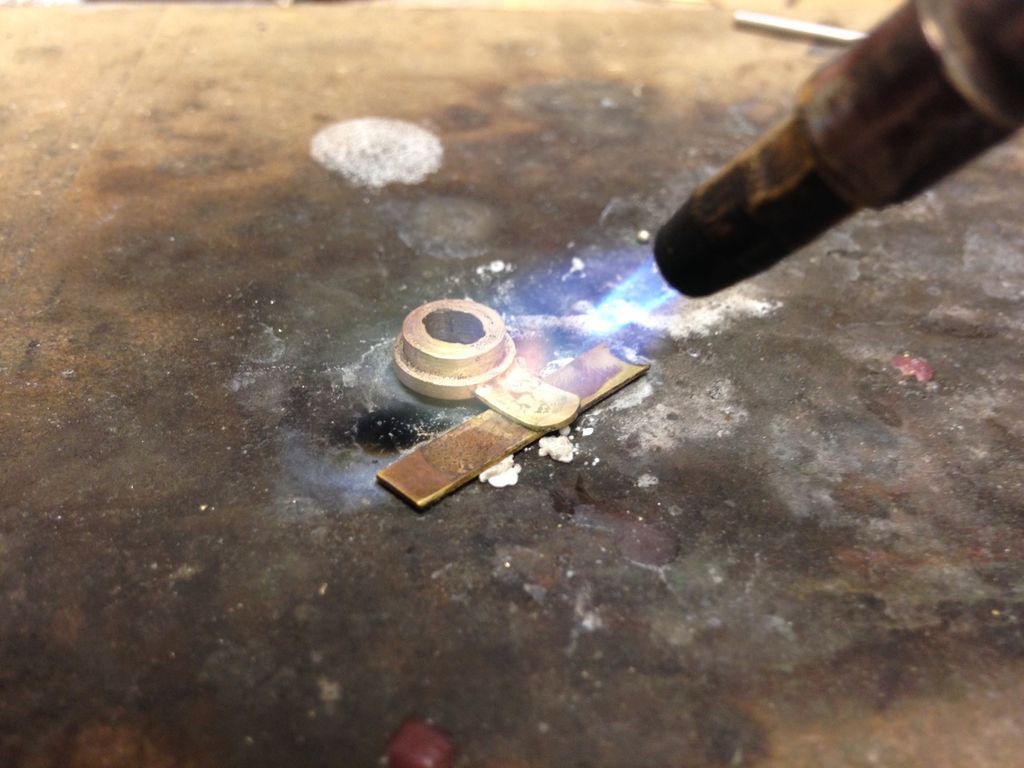
The finished tab soldered into place. The hole is for a small wood screw.
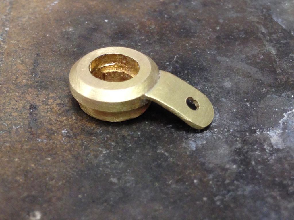
Test fitting the finished photocell holder.
Cutting out the brass plate for the force sensitive resistor. This was then annealed and bent to shape on the wood screwdriver body.
Engraving the brass plate with an old pantograph engraving machine.

The finished curved plate with my son's initials engraved.
The finished plate with the force sensitive resistor held underneath. The end of the resistor reaches the inside of the wood body through a small slot cut under the plate with a Dremel tool.
Discussions
Become a Hackaday.io Member
Create an account to leave a comment. Already have an account? Log In.