 jeromekelty
When designing the electronics for this I wanted to use as many off the shelf parts as possible so anyone could build it and easily modify it. The way the system works is the Arduino reads the sensors and spits out a value to the OpenLog to log it on the micro SD card. The value from the photocell is used to determine the amount of light available and then the white LED lights up accordingly. The force sensor reads finger pressure on the pad and then triggers the blue LED and sound effect. It's really a pretty simple circuit and it's easy to substitute or add all different types of analog sensors. I definitely recommend building the circuit on a breadboard first and running your code in order to make sure everything is working properly.
While the circuit design is relatively simple building it requires a bit of patience...
There's a lot of hardware that has to fit in a very small space and soldering all of the point to point connections can be a bit tricky when trying to make everything fit on a small piece of prototyping board. If you have some soldering experience you'll be OK but it's definitely not a job for a beginner.
I began by soldering the Arduino in place first, followed by the step up voltage regulator. The Arduino Pro Mini I used is the 5V version but the 3.3V version can be used as well- you just need to change two small details in the code (noted in the code) and change how the power from the step up converter is run. On the 5V version the power from the step up converter is connected to Vcc but on the 3.3V Pro Mini it needs to be connected to the Raw pin. That's the only difference so it's pretty easy to adapt it to whatever version you want to use- use whichever version best supports the voltage requirements of the sensors you want to use.
Once the Pro Mini was soldered in place I soldered in a header for the OpenLog. The OpenLog needs to be removable as the same pins that are used to program the Arduino are the pins used to send data to the OpenLog. On the underside of the board I connected these pins using thin gauge magnet wire in order to save as much space as possible. To protect the thin wires from abrasion (and possibly causing a short) I first put down a small strip of Kapton tape before soldering the wires in place. Once the wires were soldered I put another layer of Kapton tape over the wires. Kapton tape is awesome stuff- it stays put really well and the heat from the soldering iron won't damage it. You can also use it to hold wires in place while soldering, which is pretty handy.
Assembling the rest of the circuit is pretty straight forward. I tried to use the thinnest, most flexible wire possible in order to save space and reduce wire lengths by combining common power and ground lines. When I first wired up the temperature and humidity sensors with the LED in the nose piece I used wires that were too stiff so I later replaced these wires with some thin ribbon cable. I fully rebuilt this circuit twice in my quest to get everything to fit in the screwdriver body.
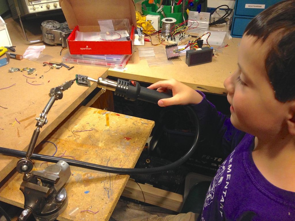
My family bought me a hot air rework station for Christmas this past year and let me tell you they are an awesome tool for taking apart circuits when you need to heat multiple connections at the same time in order to pull things apart. They are also also killer for heating up heat shrink tubing- make sure to use heat shrink on all of the connections to avoid causing a short circuit!
Once I got the circuit finished I powered it up and tested it out- worked like a charm! I was able to read data from the sensors and everything functioned as it should. Next I carefully stuffed the electronics inside the screwdriver body- and it didn't fit. Again. Darn it!
As it turned out the wires needed to be a certain length in order to be able to connect everything and be able to pull it apart and they took up too much space in the rear housing section with the USB charging circuit. Fortunately the solution was pretty simple- I just removed the charging circuit and made a two pin power connector using some header pins. That way I could just pull open the rear section of the screwdriver and connect the battery to the external charging circuit. In the future I might modify it so I just have a two pin charging jack on the screwdriver body so it doesn't have to be taken apart. Right now the power switch is press fit into a slot cut in the wood body as I haven't yet found a way to mount it to the body that looks good but I have a couple of ideas in the works...
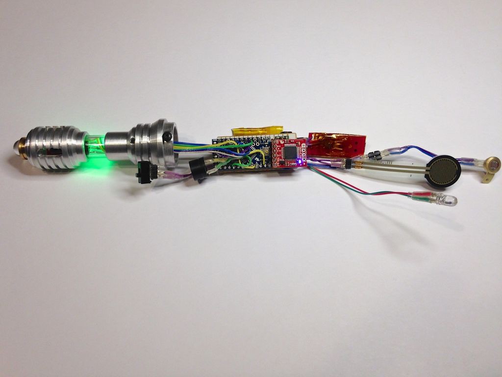
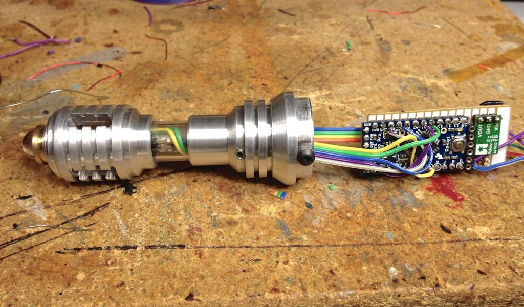
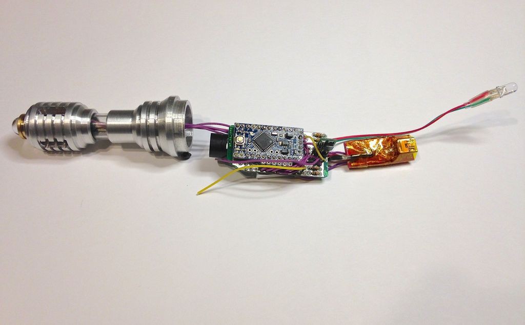
Here's the finished electronics. The RGB LED is displaying temperature. The small square red board is the OpenLog.
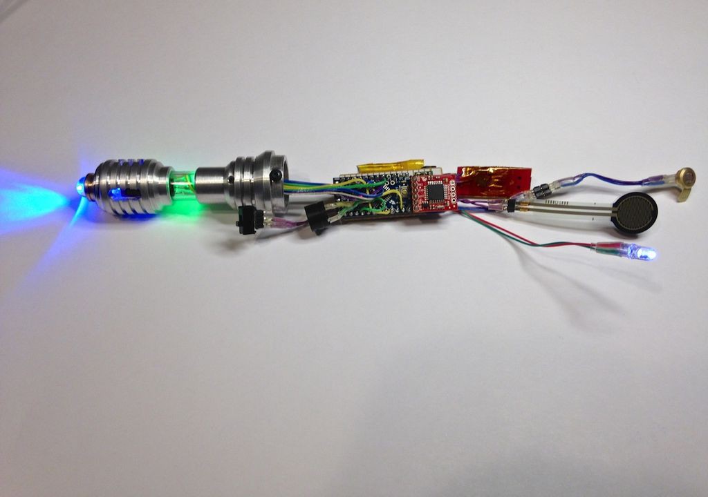
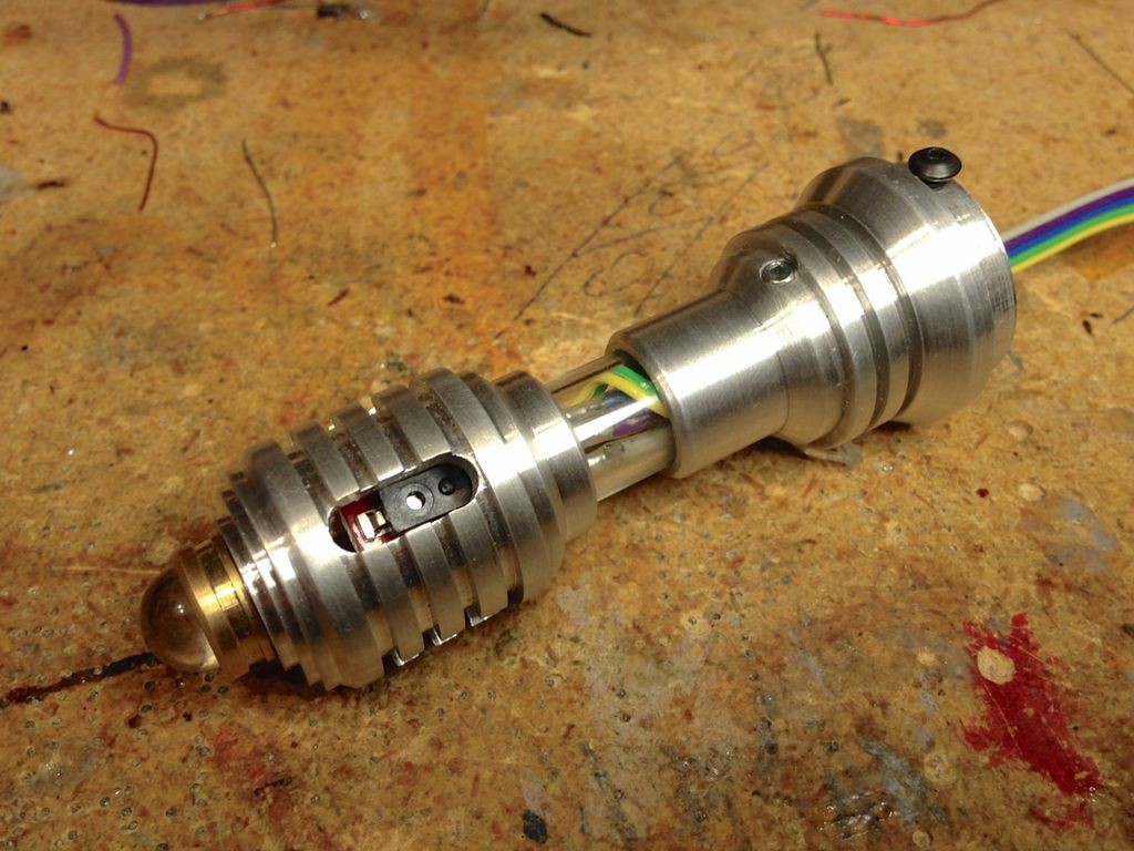
In this photo you can see the blue LED "sonic" function and the photocell LED lit up.
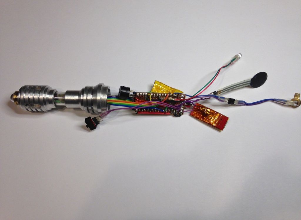
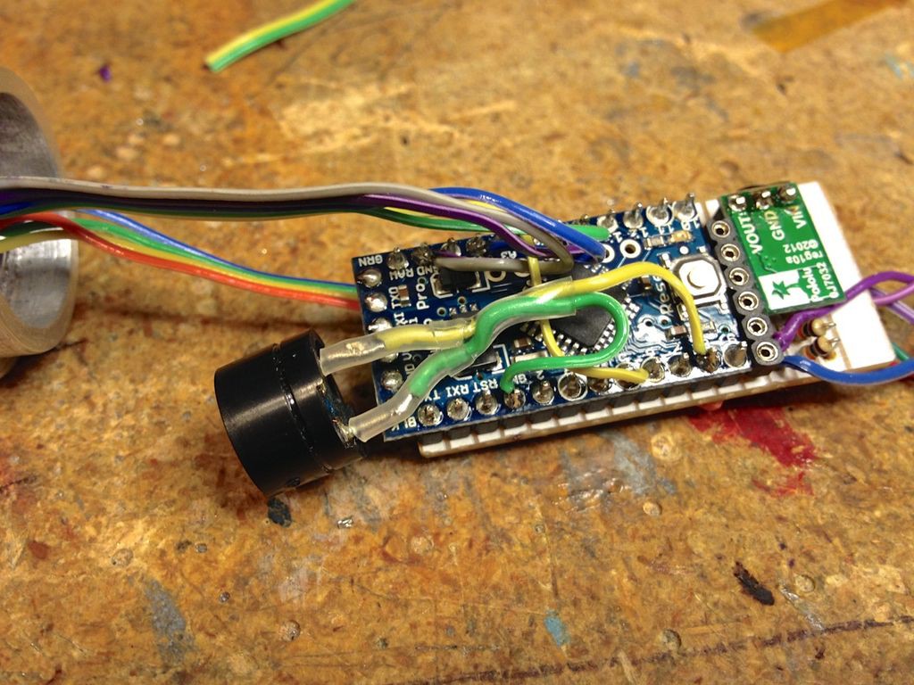
Here you can see the back side of the circuit board and the piezo that makes the "sonic" sound.
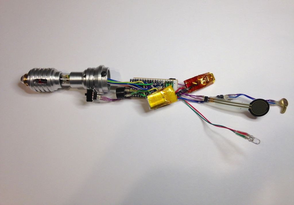
Here you can see the 110mAh 3.7V LiPo cell. This is the largest battery that would fit in the enclosure. The USB charging circuit was later removed due to space limitations.
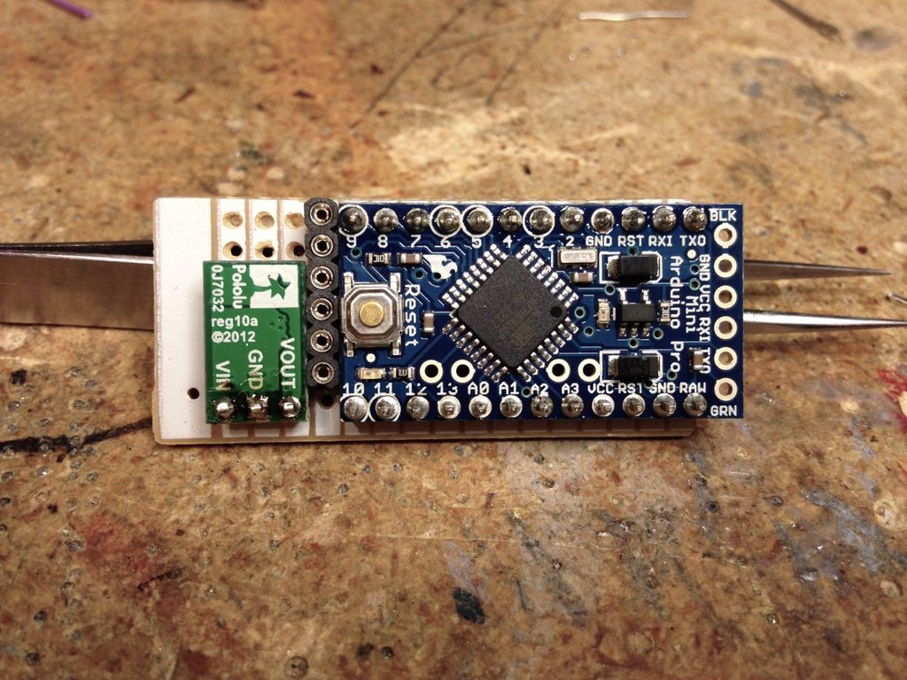
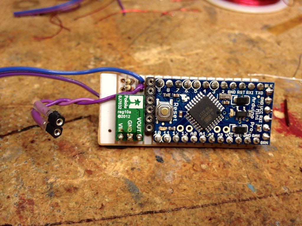
Circuit under construction. Here you can see the Arduino Pro Mini, Pololu 5V step up regulator and header for the OpenLog (which was also used to program the board using a FTDI breakout board.)
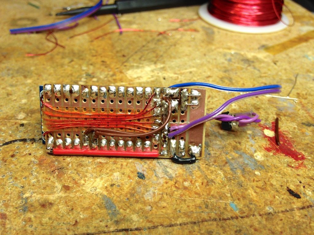
Back side of the stripboard showing wires connecting pins from the OpenLog header to the ProMini. Kapton tape underneath keeps the wires from rubbing against the board.

The OpenLog board plugged into the header.
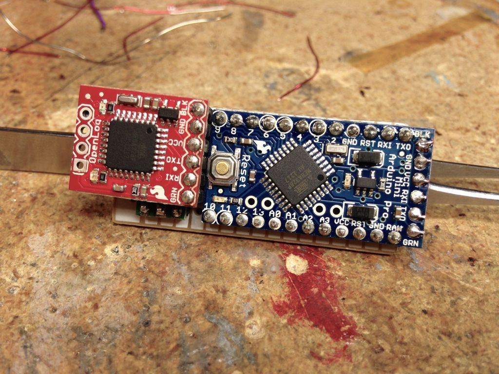
The OpenLog just clears the step up voltage regulator.
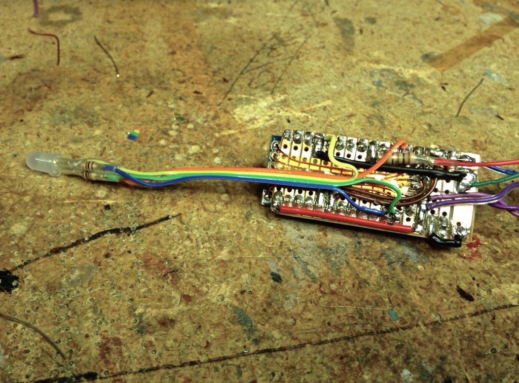
Adding power, ground and sensor wires.
Wiring up the RGB LED.
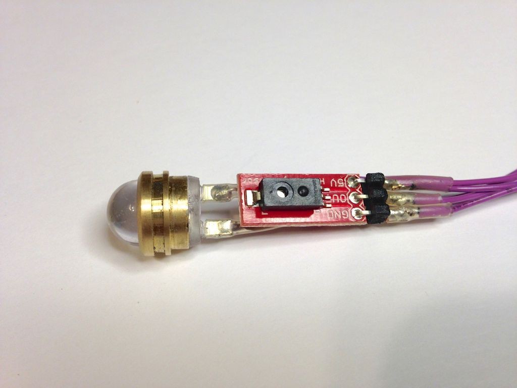
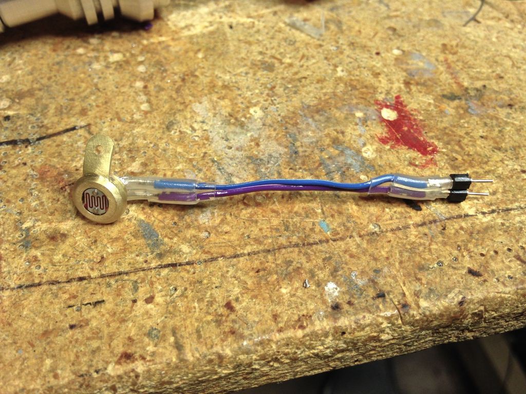
This shows the connector pins for the force sensitive resistor. The connector for the photocell is identical.
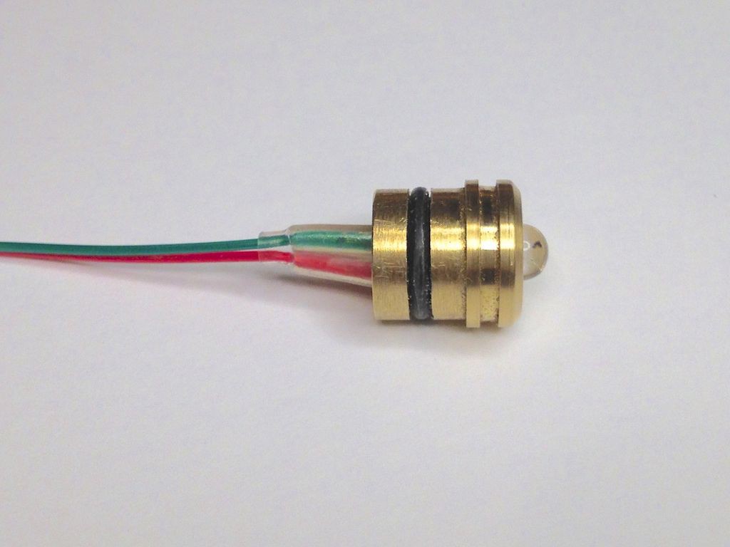
Wiring up the 5mm white LED.
Wiring the humidity sensor.
Wiring the 10mm blue LED and the temp sensor.

Fitting the LED and sensors into the nose piece. You can just see the humidity sensor. The purple wires proved to be too heavy/stiff and were later replaced with thinner ribbon cable.

Assembling the front of the Screwdriver.
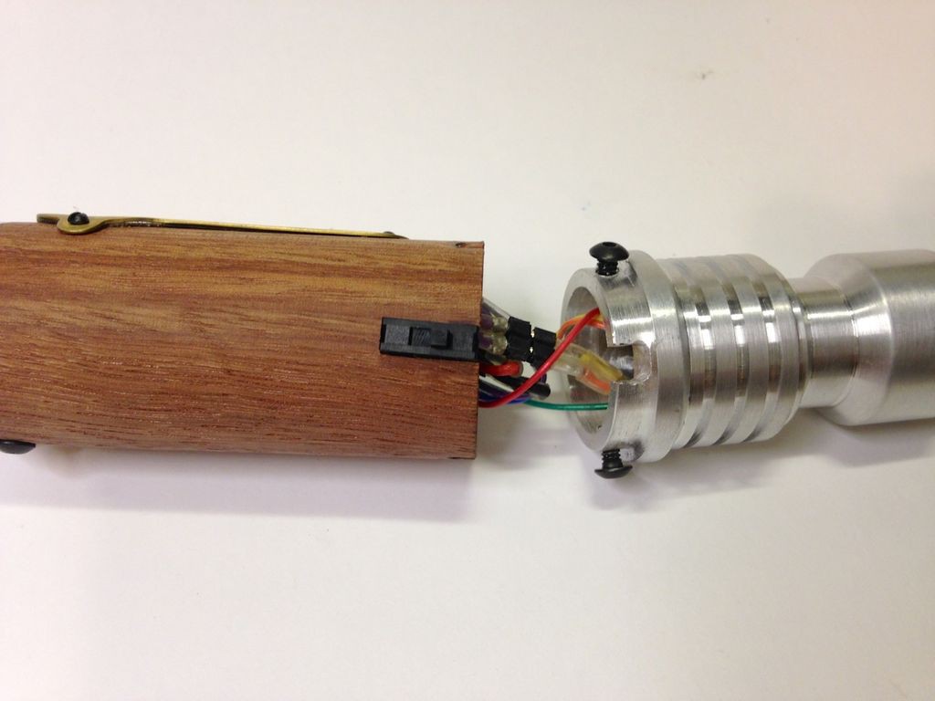
The forward section completely wired up. Here you can see the new ribbon cable. It's really important here to label all of the wires before running them through the Aluminum section so you know what goes where!
Wiring up the photocell.
Connecting the piezo.
The completed circuit ready for final testing!

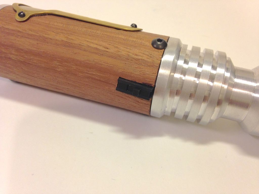
In order to fit the small slide switch a slot was cut into the wood body and the rear Aluminum piece was notched for clearance. 4-40 button head screws hold the rear Aluminum piece in place.
The slide switch installed.
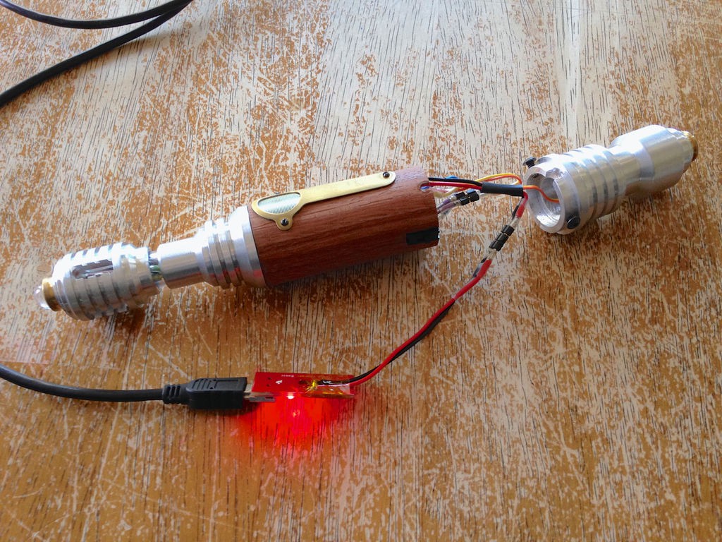
Due to space limitations the single cell LiPo charging circuit had to be left out of the body. Charging is done by removing the rear Aluminum piece and plugging the charger into a two pin connector.
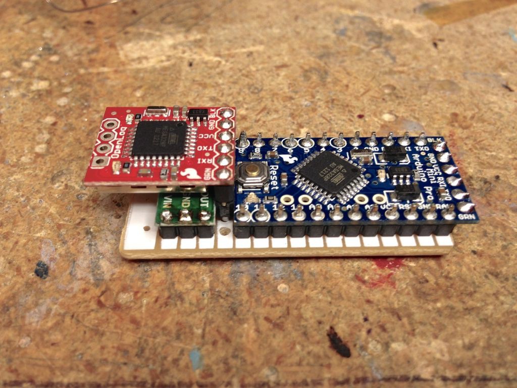
This was an earlier version of the electronics assembly. Here you can see the step up voltage regulator board sticks straight up and the OpenLog is placed on the bottom of the board. I even removed the JST connector from the charging circuit in order to try and get everything to fit but it just wouldn't work and we had to re work the circuit board layout to make it more compact.
Sam using the hot air tool to help take apart the first version circuit. He really likes this tool! We practiced removing parts from old computer motherboards first to get used to the tool.
Discussions
Become a Hackaday.io Member
Create an account to leave a comment. Already have an account? Log In.