 jeromekelty
Programming is super simple if you're already familiar with Arduino. Just remove the OpenLog from the connector and connect a FTDI breakout board (or cable) to the header pins on the board to upload your code. When you're finished uploading the code just plug the OpenLog board back into the header. Make sure that your FTDI connector voltage matches that of the Arduino you're using. If you're not familiar with Arduino I wrote up a short guide here that will help you get started.
If everything loads properly the RGB LED should light up. The LED will change color as the temperature changes- when it's really cold it'll turn bright blue, then shift to green as it warms up and finally to bright red as it gets hot. When the force sensitive resistor is firmly pressed the large blue LED will light up and a tone will play. I kept it to a single tone as the sound effect from the TV show makes my dog go nuts- she hates it and runs away so I couldn't do that. I tried a lot of sounds and this tone didn't seem to bother her. When the photocell is covered by a finger the white LED will light up to full brightness and as more light is available the white LED will dim until it turns off.
To obtain the logged sensor data just remove the SD card from the OpenLog and download the .TXT files to your computer. If you want you can export the data to Plotly and make all kinds of cool graphs, make a Google Chart or upload it to the Sparkfun data site.
There are notes in the code about various connections and how to modify the code if you're using a 3.3V board.
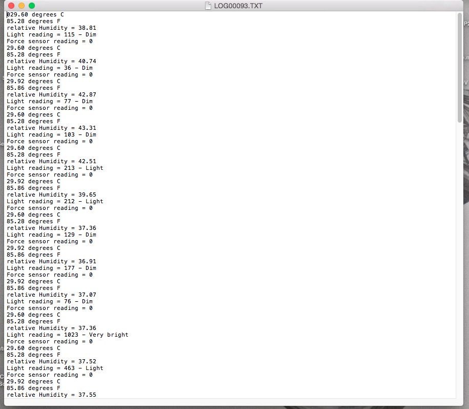
Sensor readings recorded by the OpenLog.
Entering logged values in Plotly.

Plotly allows you to graph data in all sorts of different ways.

Here's the code-
//TMP36 Pin Variables
int sensorPin = 0; //the analog pin the TMP36's Vout (sense) pin is connected to
//the resolution is 10 mV / degree centigrade with a
//500 mV offset to allow for negative temperatures
int sensorVal = 0;
int HIH4030_Pin = 1; // humidity sensor is connected to analog pin 1
int photocellPin = 2; // photocell is connected to analog pin 2
int photocellReading;
int fsrSensor = 3; // the FSR sensor is connected to analog pin 3
int threshold = 600; // threshold value to decide when the sensor input triggers
int ledPin = 5; // blue 10mm LED connected to pin 5
int fsrReading = 0;
int redPin = 9; // RGB LED red connected to pin 9
int greenPin = 10; // RGB LED green connected to pin 10
int bluePin = 11; // RGB LED blue connected to pin 11
int whtPin = 6; // white LED connected to pin 6
int whtbrightness;
int blueTemp= 0; int greenTemp= 0; int redTemp= 0;
int speakerPin = 8; // piezo connected to pin 8
void setup()
{
Serial.begin(9600); // Start the serial connection with the computer
// to view the result open the serial monitor
Serial.print(millis()); // print time in milliseconds
pinMode(ledPin, OUTPUT); // sets the blue 10mm LED pin as output
digitalWrite(ledPin, LOW);
}
void loop() // run over and over again
{
//getting the voltage reading from the temperature sensor
int reading = analogRead(sensorPin);
// converting that reading to voltage, for 3.3v arduino use 3.3
float voltage = reading * 5.5;
voltage /= 1024.0;
// now print out the temperature
float temperatureC = (voltage - 0.5) * 100 ; //converting from 10 mv per degree with 500 mV offset
//to degrees ((voltage - 500mV) times 100)
Serial.print(temperatureC); Serial.println(" degrees C");
// now convert to Fahrenheit
float temperatureF = (temperatureC * 9.0 / 5.0) + 32.0;
Serial.print(temperatureF); Serial.println(" degrees F");
if(temperatureC<0){
analogWrite(bluePin, 255);}
else if(temperatureC>0&&temperatureC<=25){
blueTemp= map(temperatureC, 0, 25, 255, 0);
analogWrite(bluePin, blueTemp);}
else if(temperatureC>25){
analogWrite(bluePin, 0);}
if(temperatureC<10){
analogWrite(greenPin, 0);}
else if(temperatureC>13&&temperatureC<=30){
greenTemp = map(temperatureC, 13, 27, 1, 254);
analogWrite(greenPin, greenTemp);}
else if(temperatureC>13&&temperatureC<=27){
greenTemp = map(temperatureC, 13, 27, 255, 0);
analogWrite(greenPin, greenTemp);}
else if(temperatureC>27){
analogWrite(greenPin, 0);}
if(temperatureC<26){
analogWrite(redPin, 0);}
else if(temperatureC>=24){
redTemp= map(temperatureC, 24, 38, 1, 255);
analogWrite(redPin, redTemp);}
else if(temperatureC>38){
analogWrite(redPin, 255);}
delay(200); //wait 200 ms before sending new data
//To properly caculate relative humidity, we need the temperature.
float temperature = temperatureC; //replace with a thermometer reading if you have it
float relativeHumidity = getHumidity(temperature);
Serial.print("relative Humidity = ");
Serial.println(relativeHumidity);
photocellReading = analogRead(photocellPin);
Serial.print("Light reading = ");
Serial.print(photocellReading); // the raw analog reading
// We'll have a few threshholds, qualitatively determined
if (photocellReading < 10) {
Serial.println(" - Dark");
} else if (photocellReading < 200) {
Serial.println(" - Dim");
} else if (photocellReading < 500) {
Serial.println(" - Light");
} else if (photocellReading < 800) {
Serial.println(" - Bright");
} else {
Serial.println(" - Very bright");
}
// wht LED gets brighter the darker it is at the sensor
// that means we have to -invert- the reading from 0-1023 back to 1023-0
photocellReading = 1023 - photocellReading;
//now we have to map 0-1023 to 0-255 since thats the range analogWrite uses
whtbrightness = map(photocellReading, 0, 1023, 0, 255);
analogWrite(whtPin, whtbrightness);
// read the fsr sensor and store it in the variable fsrReading:
fsrReading = analogRead(fsrSensor);
Serial.print("Force sensor reading = ");
Serial.println(fsrReading);
// if the sensor reading is greater than the threshold:
if (fsrReading >= threshold) {
digitalWrite(ledPin, HIGH);
tone(8,250,1600); // Play a 250 Hz tone for 1.6 seconds
}
else if (fsrReading < threshold) {
digitalWrite(ledPin, LOW);
noTone(8);
}
delay(2000); //wait two seconds
}
float getHumidity(float degreesCelsius){
//caculate relative humidity
float supplyVolt = 5.5; // for 3.3v arduino use 3.3
// read the value from the sensor:
int HIH4030_Value = analogRead(HIH4030_Pin);
float voltage = HIH4030_Value/1023. * supplyVolt; // convert to voltage value
// convert the voltage to a relative humidity
// - the equation is derived from the HIH-4030/31 datasheet
// - it is not calibrated to your individual sensor
// Table 2 of the sheet shows the may deviate from this line
float sensorRH = 161.0 * voltage / supplyVolt - 25.8;
float trueRH = sensorRH / (1.0546 - 0.0026 * degreesCelsius); //temperature adjustment
return trueRH;
}
Discussions
Become a Hackaday.io Member
Create an account to leave a comment. Already have an account? Log In.