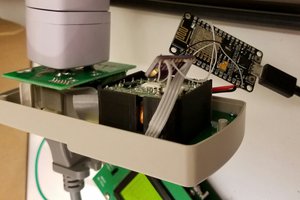
The setup
This is still in its development phase but the plan is to measure the power from the PV array, with a grid-tie inverter, and the power imported/exported from grid and to allow use of the excess generated power. This could go to a heater in workshop in winter or preheat water for the boiler. I have a combi boiler that allows preheat but this will need plumbing in. I had taken the old tank out, but kept it with much annoyance from the wife, planning ahead!?
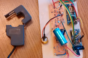
Measurements
Do I count the pulses at the meter or measure voltage and current. For data logging purpose counting the pulses would be fine. Pulses over a fixed time (5 mins or 1 min) a trade off between amount of data and detail. Counting time between pulses may be too much detail.
Yet for power diversion this would probably not be accurate enough so voltage and current sampling will be needed. This then brings in the complication of phase correction as the samples are taken at different times.
Data logging
Should be simple.
Power diversion
This requires some more research on the control but in essence I switch a triac on and off so the meter does not charge me nor do I export any of my energy.
Power storage
Still to be considered but this will need battery banks, charge controller, inverter and a means of switching power sources. Also to be considered would be dedicated DC circuits in the house.
 OLEKSIY
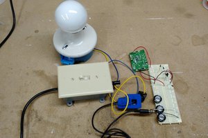
 CaptMcAllister