 kevarek
This is not fail as such, but I believe it is good lesson learned and also trick to have in a sleeve, so I will publish it here (maybe just for future myself being lost again).
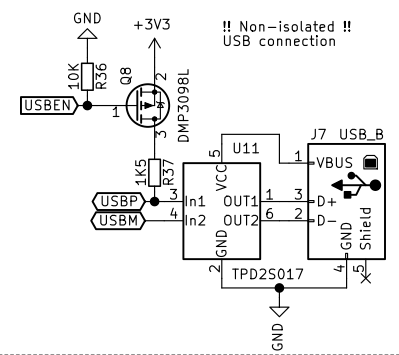
When connecting MCU to PC via USB, it is quite useful to fit external pull-up resistor in series with MCU controlled PFET to 3.3V supply. This allows you to turn the pull-up off and on during MCU boot and inform USB hub to re-enumerate your device without re-inserting the connector (for instance during debugging sessions).
A USB device must indicate its speed by pulling either the D+ or D- line high to 3.3 volts. A full speed device, pictured below will use a pull up resistor attached to D+ to specify itself as a full speed device. These pull up resistors at the device end will also be used by the host or hub to detect the presence of a device connected to its port. Without a pull up resistor, USB assumes there is nothing connected to the bus. Some devices have this resistor built into its silicon, which can be turned on and off under firmware control, others require an external resistor.
https://www.beyondlogic.org/usbnutshell/usb2.shtml
 Well few days ago, while reusing one of my very old and obsolete PCB without external switchable pull-up, I had to write new firmware and each debug session start I had to re-insert the connector, which was mind numbing and after some time I started to look for software workaround. Im not sure whether this is USB compliant hack, but it certainly works.
Before initializing USB peripheral in MCU, D+ pin (USBP) is configured as GPIO output push-pull and set low (0V) for 5ms. After that standard USB configuration including GPIO is performed. After this procedure USB host recognizes new device and starts enumeration.
/*******************************************************************************
                       LL Driver Callbacks (PCD -> USB Device Library)
*******************************************************************************/
/* MSP Init */

void HAL_PCD_MspInit(PCD_HandleTypeDef* pcdHandle)
{
  GPIO_InitTypeDef GPIO_InitStruct;
  if(pcdHandle->Instance==USB)
  {
  /* USER CODE BEGIN USB_MspInit 0 */

    GPIO_InitStruct.Pin = GPIO_PIN_12;
    GPIO_InitStruct.Mode = GPIO_MODE_OUTPUT_PP;
    GPIO_InitStruct.Pull = GPIO_NOPULL;
    GPIO_InitStruct.Speed = GPIO_SPEED_FREQ_HIGH;
    HAL_GPIO_Init(GPIOA, &GPIO_InitStruct);
    HAL_GPIO_WritePin(GPIOA, GPIO_PIN_12, GPIO_PIN_RESET);
    HAL_Delay(5);

  /* USER CODE END USB_MspInit 0 */

    /**USB GPIO Configuration
    PA11     ------> USB_DM
    PA12     ------> USB_DP
    */
    GPIO_InitStruct.Pin = GPIO_PIN_11|GPIO_PIN_12;
    GPIO_InitStruct.Mode = GPIO_MODE_AF_PP;
    GPIO_InitStruct.Pull = GPIO_NOPULL;
    GPIO_InitStruct.Speed = GPIO_SPEED_FREQ_HIGH;
    GPIO_InitStruct.Alternate = GPIO_AF14_USB;
    HAL_GPIO_Init(GPIOA, &GPIO_InitStruct);

    /* Peripheral clock enable */
    __HAL_RCC_USB_CLK_ENABLE();

    /* Peripheral interrupt init */
    HAL_NVIC_SetPriority(USB_LP_IRQn, 5, 0);
    HAL_NVIC_EnableIRQ(USB_LP_IRQn);
  /* USER CODE BEGIN USB_MspInit 1 */

  /* USER CODE END USB_MspInit 1 */
  }
}
I hope this helps someone in the future. Im wondering whether this is fully compliant routine to re-enumerate USB device and Im using external pull-up and PFET all the time redundantly? Please comment if you know the answer :)
Discussions
Become a Hackaday.io Member
Create an account to leave a comment. Already have an account? Log In.
Hello! I have mosfet AOL3401A. Is it a good replacement (one to one in that circuit) for dmp3098l?
Are you sure? yes | no
Thanks for posting these! I had one loosely related problem: working-from-home on USB circuit on my desk at work. I needed to be able to "re-plug" not only my device, but also my debugger hooked up to it. I found a USB hub (Yepkit) that would allow me to disconnect either or both from USB and reconnect at will.
Are you sure? yes | no
Been there because other chips I used have built-in programmable pull-ups. :(
There is a cheat to save the MOSFET and the GPIO needed. It is not as clean. The USB data line is pulled up to 3.3v via the 1.5K directly. The pin is set as GPIO output Low for disabling and config as USB to enable. for bare metal, the GPIO mode is set from the GPIO CRH register. :)
This is the same trick used on software bitbang V-USB for ATMega.
If you want, you could tie the 1.5K to a GPIO output (to save 1 MOSFET). Set it high to enable; tristate to disable.
The other USB data line can be used by firmware for polling if it has been connected to a USB port by setting as an GPIO input with internal pull up. The 15K pull down from the Host port (when connected) will pull the signal to Low.
I used these tricks on one of my current projects.
Are you sure? yes | no