 Sci
SciandNote: I've changed the project description. The Stratasys is actually only 22 years old, not 30. This discovery comes later.
I'd already looked over the Stratasys parts when I pulled them from the original housing and I'd estimated I could likely fit the parts inside the fridge after removing some of the excess housing material.
The way the mechanics of the FDM 1650 had been built was as an aluminium plate box containing the vertical axis/bed with an existing pick & place machine on top holding the print head.
The pick & place machine was an Asymtek Automove 302.
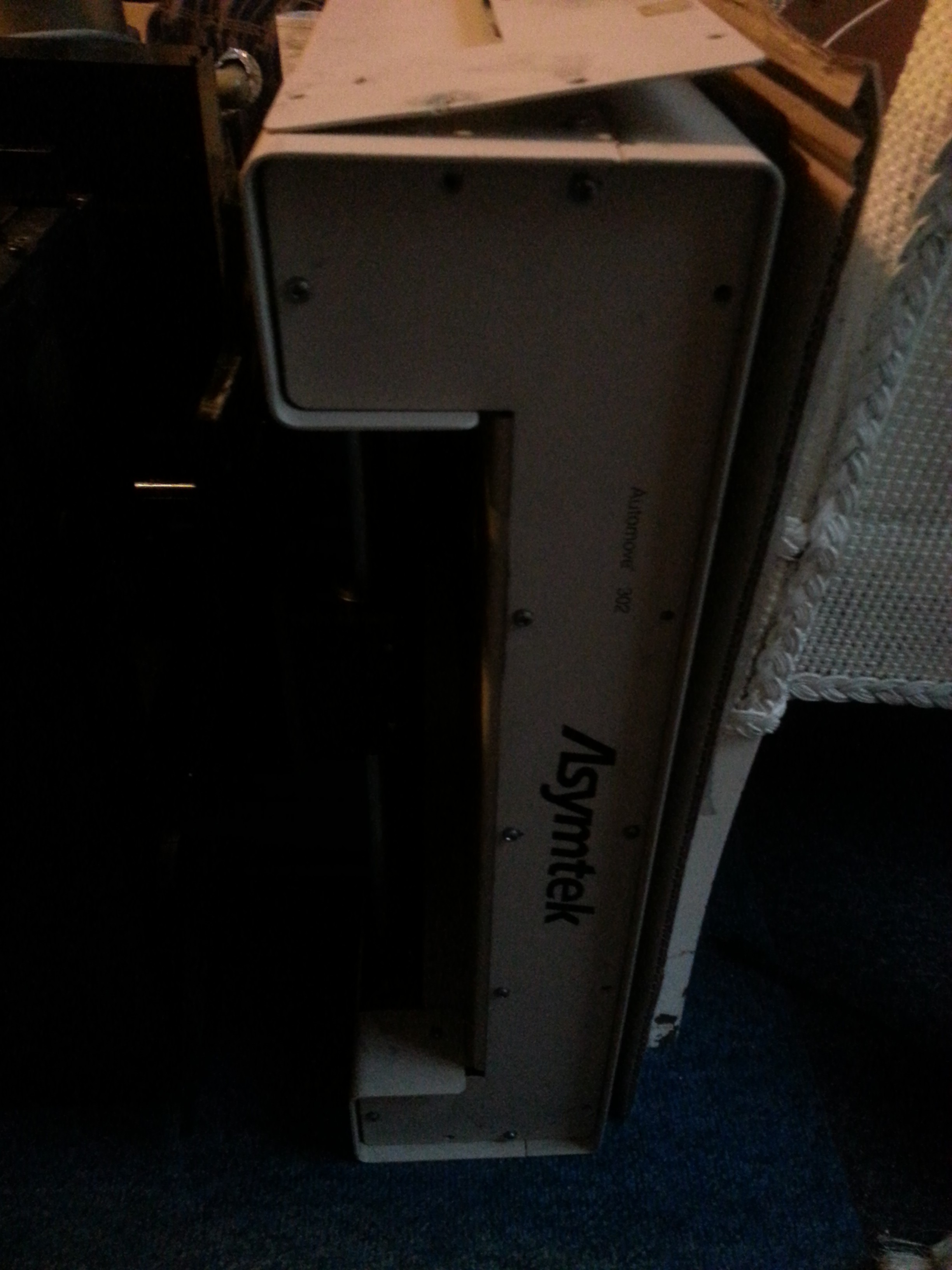
That's it's rear panel sitting on top of it. It was already off when I got to it, and the wires connecting to it had already been cut.
On it's own, that wouldn't have been too bad. There's no smarts inside it. The sum total of the electronics within consists of two stepper motors and an endstop board.
That wasn't the only problem though. In addition, I'm in the UK. This was made in the USA. Not only are all the parts and fittings imperial, they're American imperial. And half the screws are either missing, sheared off or have heads that are totally chewed up. It was easier to dismantle the housing than open the service panel.
 Okay, that actually looks pretty good!
The whole thing is run with a clever web of plastic-coated steel cables and threaded capstans. The rails are really chunky at 19mm..? No, 3/4" thick exactly. And exactly 19" long.
Perhaps I could just transfer it all to a nice thick aluminium plate with a hole in the middle. Can I move the position of the motors though? Let's have a closer look at the cable.
Oh.
(I'll put the picture here when I find where I saved it)
I knew the plastic on the cable was a bit cracked, but it actually worse than I thought. It's flaked off completely in a lot of places and the cable has actually started to unwind in one portion. And this has been running over the aluminium capstans, which has left them pretty chewed up.
So the cable needs replacing. That's tricky, since it needs to be just the right length & thickness as well as plastic coated. But it's doable if I can find the right supplier. So I'll unhook it to measure it. That means I can check the pulleys too.
(I'll put the picture here when I find where I saved it)
Oh.
That's about a 2mm groove the cable's worn in the pulley over the years. It's hard to tell if the muck either side is pulverised plastic or hardened grease.
Some of the pulleys are okay, but about a third of them will need replacing, which means making new ones. And the bearings they're mounted on are wobbly, so the bearings all need replacing too.
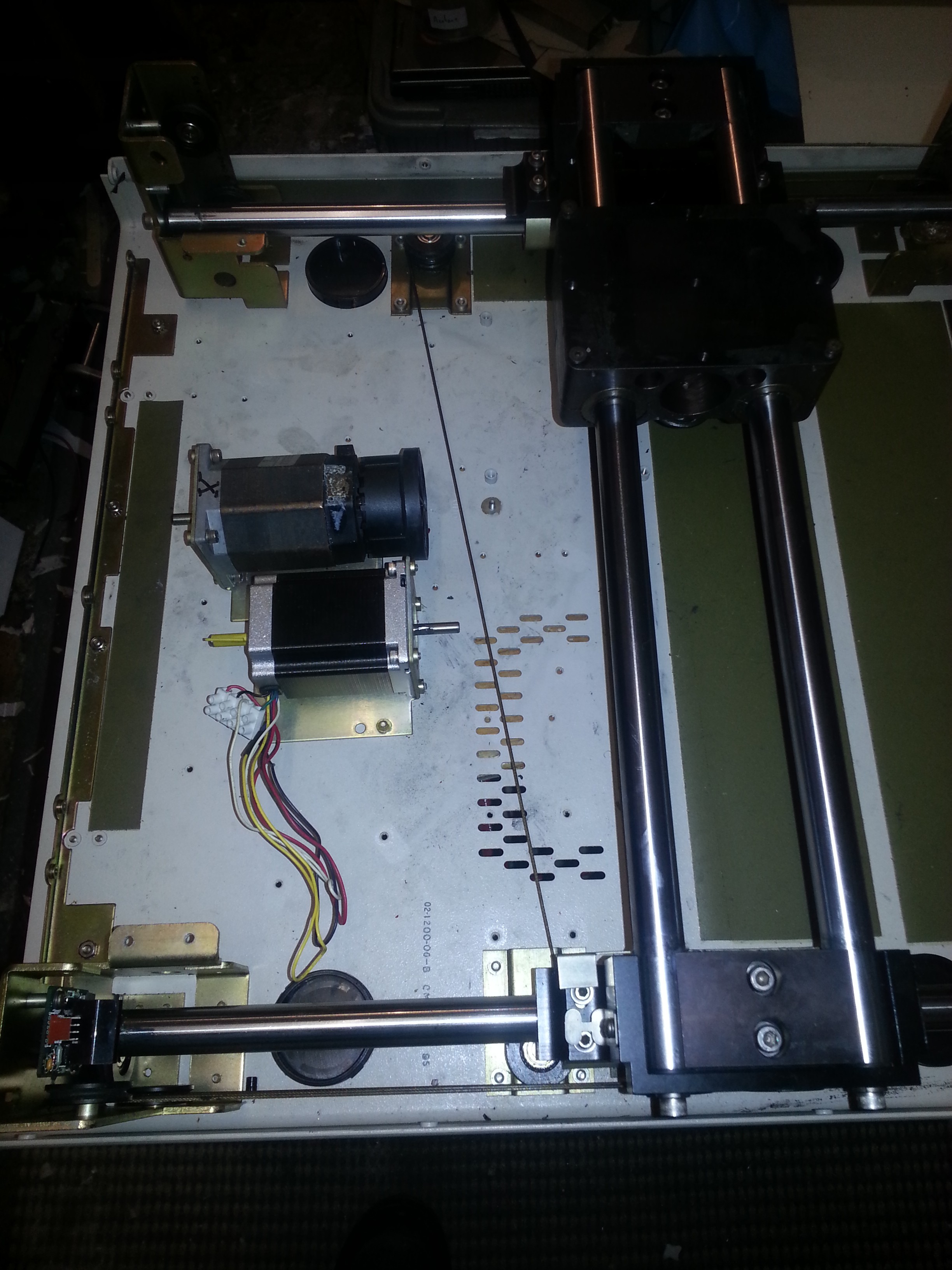
So with the cable removed, I decided to check the linear bearings. The X axis and the two sides of the Y axis.
One Y axis rail runs fine, the other sounds like it's full of sand and has some axial play. The X runs, but runs rough. So the bearings are all on their last legs.
No, it's ALL on it's last legs.
Ugh.
It's time for a change of plan.
I could, in theory, replace/remanufacture all the parts and rebuild the mechanics as they were originally. But to find the imperially sized parts will put the cost up, especially those large linear bearings. It'd cost less to build it from scratch. And if I'm doing that I can build something better.
So, what about the vertical axis? Is that usable at least?
Well, it's more usable.
Quarter and 1/8" anodised aluminium plate, four leadscrews with 1/8" pitch synchronisned belt drive from one stepper giving a 1/2000" resolution per full step. That would be very good layer resolution.
This was the one that used to blow the driver boards though. The stepper drew too much current. And looking at the weird way they arranged the linear guide makes it obvious why. It's not a linear bearing. It's a rail on either side and a fat tensioning screw that clamps onto them. So the less play you want, the harder the motor will have to push.
(I'll put the picture here when I find where I saved it)
So at very least a proper linear bearing needs to go there. Which means changing the rails out for a metric ones, which means modifying the mounts. And this would be to enable me to keep using the 22yo ballscrews. Which need to come out anyway because the supporting bearings are caked in molten plastic.
I'm not going to "grandfathers axe" this. About all that's here that's actually useful for a precise and reliable 3D printer is a single stepper motor, some aluminium plate and maybe some toothed pulleys.
The Stratasys guts I salvaged are only good for inspiration and scrap metal.
I even checked the heaters. There's four of them, all 900Watt. This thing used 3600Watts just for heating the build chamber.
One of the fans though did have a manufacturing date of 1995. So at least that corrects the age of the original machine.
So next up: designing a stratasys-inspired 3D printer from scratch.
Discussions
Become a Hackaday.io Member
Create an account to leave a comment. Already have an account? Log In.