 Nathaniel VerLee
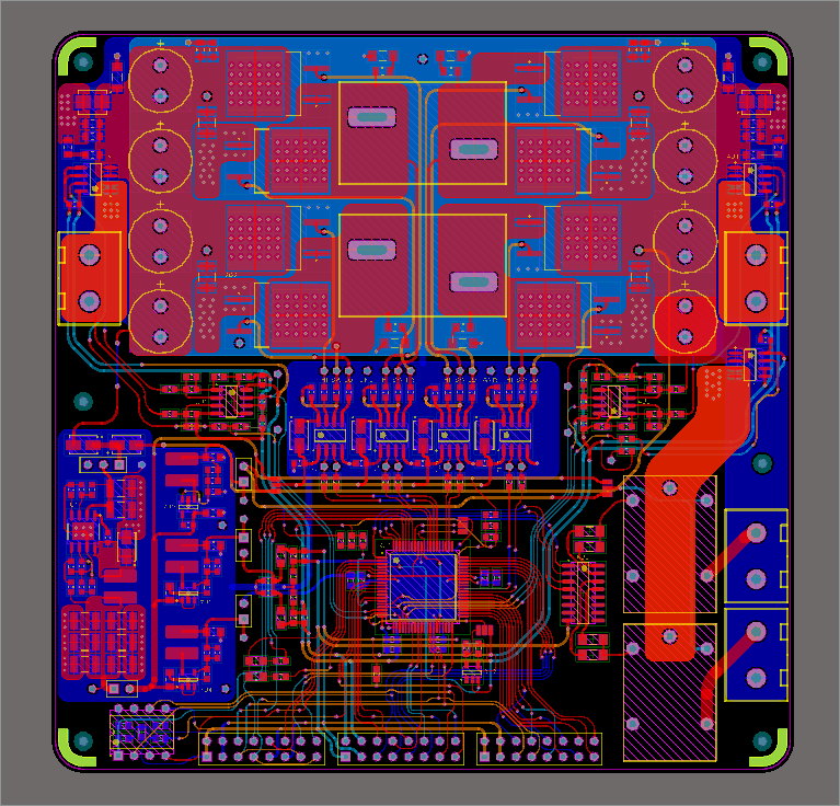
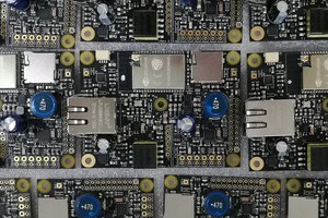
The solar energy generator has a buck boost topology DC-DC converter that can either step up or step down the output voltage from the input voltage, which allows the system to operate at the panels peak efficiency known as the maximum power point. The maximum power point is tracked using a current and voltage sensor by periodically changing the input to output voltage relationship of the DC-DC converter and measuring the corresponding changes in output power the sensors. In addition to implementing Maximum Power Point Tracking, the buck boost topology allows the battery operating voltage range to be either higher, lower, or both relative to the panel input voltage depending on the solar panels used. When configured properly it can be used to harness the energy of panels up to 500W in capacity. Batteries capacities can be anywhere from 100 watt hours to a few kilo-watt hours in capacity, and the initial target battery chemistry is lithium iron phosphate due to its high cycle life and increased safety over traditional lithium cells. Other chemistries such as lead acid will also be supported in the future. The generator is composed of the following circuit blocks: a two phase buck boost DC-DC converter, a battery current sensor, a load current sensor, a battery voltage sensor, gate drivers for the converter, a C2000 micro controller, 12V, 5V, 3.3V and 1.8V rails, and a load switch.
A load switch is critical to protecting the battery from over discharge and short circuit. The load switch opens and disconnects the load if either of these conditions should occur. Currently, this portion of the system is not fully defined and may be implemented either with relays or MOSFETs as the switch. Each of the two load switches should be able to handle at least 10A, and more may potentially be added externally.
A Texas Instruments C2000 TMS320F28035 has been selected for the final design of the project, but in the prototyping stage a TMS320F28027 is being used as it is available in a pre made "launchpad" platform from TI, which includes the necessary debugging and programming interface as well as 5V and 3.3V supplies. The C2000 microcontroller was selected because it has many features designed for digital power applications, and configuring it to drive the buck boost converter is not only easy, but powerful, allowing multiple converters to be driven in a phase relationship, and allowing for fast shut down of the converter stage in the event of a dangerous transient event. In the final single-PCB solution, a buck converter will be connected to both the panel input and the battery via a diode or, which will source power from the higher of the two voltages. This 5V rail will then supply power for a 12V rail (boost) for the FET gate drivers and the 3.3V and 1.8V rails for the micro, sensor circuits, display, and various other circuits.
Finally, the converter will include a simple character display, buttons and an encoder wheel to configures various system settings such as battery float voltage, power limiting, a load shutdown timer, display system power output, and allow for future information and configuration features. I selected an OLED display from Adafruit for its high contrast and bold appearance.
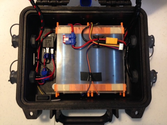
In the current stage of development the separate sensor boards, power stage board and the C2000 development board are all connected to each other in a manner very similar to the configuration of the final completed PCB. Some features are not currently available such as the load switches and the supply rails. Much of the last two months of development has been teaching myself to code for the C2000 platforms. The next stages of development will include finalizing the proof of concept with separate interconnected PCBs, finishing work on the final PCB, measuring the performance of the prototype with instruments and searching for possible improvements, and creating in depth documentation of the project.
Link to the full System Design Document can be found...
Read more »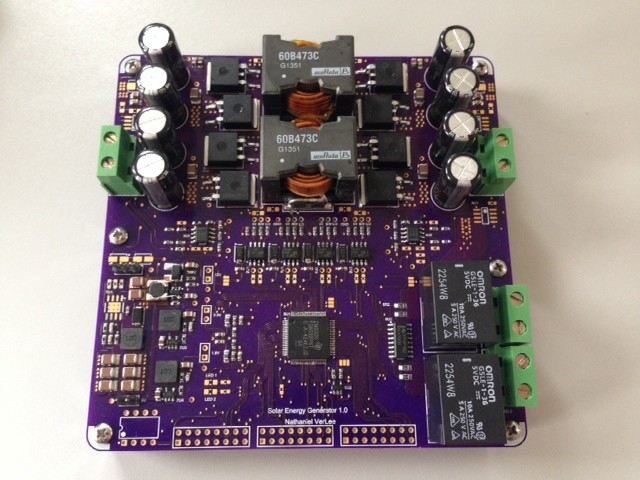


 Patrick Van Oosterwijck
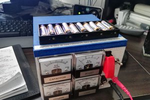
 David Scholten
 John Loeffler
 Jakob Wulfkind
Would people be interested in seeing a version 2 of this project? Would you be interested in using one and programming one if it was based on MSP430? Let me know!