 Stephen Holdaway
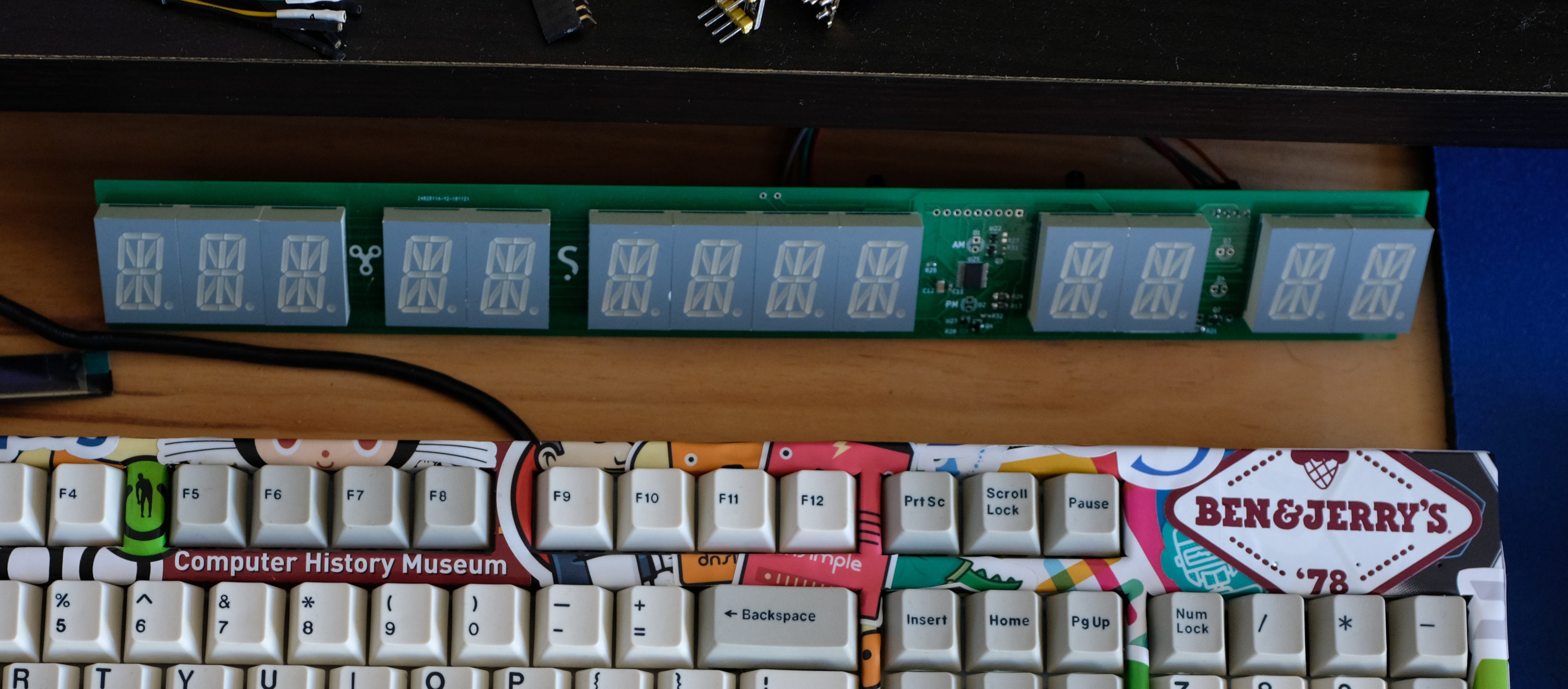
This board has been sitting on my desk for a couple of months since assembly, waiting for some debugging attention to sort out its low brightness and hot running. I finally got around to it today, prompted by someone showing interest in the build. I've been putting off debugging it because I had mentally tagged this as an unknown, probably hard electrical problem, but it turned out to be fairly straight forward.
After a couple of hours of hacking in a separate drive voltage for the display segments and some fiddling, the problem basically comes down to the power that can be sunk into the pair of TPIC6B595 shift registers used to select the active digit. Doing some back of the envelope math that I really should've done earlier, if every segment is on at the ideal drive current of 20mA, that requires:
[16 segments] x [20mA] x [13 digits] = 4.1 Amps
In a more typical scenario where an average of half the segments are on, that still requires 2A to drive. The datasheet for the TPIC6B595 power shift registers states that each one has an absolute max sink capability of 500mA. In practice, sinking even 250mA into each one on this board makes them too hot to touch. There wasn't much room for the ground plane with via stiching that the datasheet recommends to pull heat away from the chips, so that doesn't help the situation.
A bit of trace cutting and bodge soldering further demonstrated this power bottleneck for me. Boosting the supply voltage for the LED drivers between 6V and 12V gained a small amount of brightness, but made the TPICs scorching hot as they needed to sink 5+ Watts at the higher voltage. After removing the fairly low-value resistors I had on the LED driver current control pins (Rext) to increase the pulsed current from 20mA to around 60mA (in theory), changing the voltage had no impact on brightness.
I'm not entirely sure why the LED drivers aren't delivering more current even when configured to drive 60mA, but I suspect the TPIC chips' thermal regulation mentioned in the datasheet is preventing sinking too much current. Trying to drive a segment across 13 digits with the 30mA being delivered doesn't give a bright display as it's equivalent to driving a single segment with only 1.5mA.
Where to now?
There are two design options I see going forward from here:
- Create a new driver that uses descrete FETs to sink the digit current.
- Split the driving into two sections that each drive up to 7 digits. The display is an ok(-ish) brightness when the currently available power is used to drive half the digits instead of all 13.
Option two isn't ideal as it would be still be limited by the TPIC's capacity to sink, wouldn't be blazingly bright, and would require a duplicate of the segment shift registers, LED drivers and current setting resistors which adds 40+ components.
A third option would be to complete this project with the rev 2 board as a toy since I already have a digital clock in the appartment that's running all the time. I still like the idea of making a daylight-visible version of this project, but also on my mind is that it will likely cost $10 - 20 NZD each year in power alone to run a brighter version of it 24/7..
Regardless of the solution for the driver, any further revision is definitely going to involve a display board that simply exposes the segment and digit pins through a pin header. That big board is expensive, and it needs to be reusable! I was on the fence with this for rev 2 and ended up thinking "I've got it this time" so didn't bother. I did not in fact "have it this time". Not going to make that mistake again!
Discussions
Become a Hackaday.io Member
Create an account to leave a comment. Already have an account? Log In.
There is one redesign you can do but it may be too much modification. It uses the effect that when multiplexed, the apparent brightness of LEDs is higher than the product of the current and duty cycle would lead you to expect. I don't remember how large the effect is though. I also forget if it's due to the response of the human eye or that LEDs have better conversion efficiency at higher currents.
Are you sure? yes | no
Interesting - I've been multiplexing whole digits which gives a duty cycle of 1/13, but that runs up against the sinking capability of those shift registers.I'll have a play with pumping a ton of current into one segment at a time... it'll make the duty cycle 1/208, but perhaps you're right that persistence of vision can be leveraged to make this appear brighter. Thanks!
Are you sure? yes | no
There are peak current limits you may have to stay within, so you may already have used the advantage with 1/13.
Are you sure? yes | no