 Stephen Holdaway
Another year has gone by with this project waiting quietly in the bookshelf. It's time to finish it off.
The Holtek HT16K33 LED driver IC was brought to my attention in the last year, and it looks ideal for driving 16 segment displays: a 16 x 8 common-cathode driver controlled over I2C. The chip was released around 2010, but isn't (currently) listed by any US-based distributors. If I'd known about this chip at the start of the project, we would've been done and dusted years ago on the first PCB revision!
Re-spinning the display PCB is off the table as I've already spent way more than I wanted to on PCBs for this project. The current revision is still useful for mounting and connecting segments, but I'm going to need to dead-bug some HT16K33 chips as none of the footprints on the board can accommodate its 28-pin package. To drive the whole display I'll need two HT16K33 drivers.
Initial testing
To check the performance of the HT16K33 against the existing driver circuit, I borrowed 6 digits from the original assembly and wired a them along with a single HT16K33 to an unpopulated PCB. Desoldering all those digits is considerably easier now I have a proper desoldering gun, but it's still 208 joints for the whole display so takes a while.
With some I2C communication hacked into the existing STM8S firmware, I was able to do a side-by-side comparison with the original driver assembly.
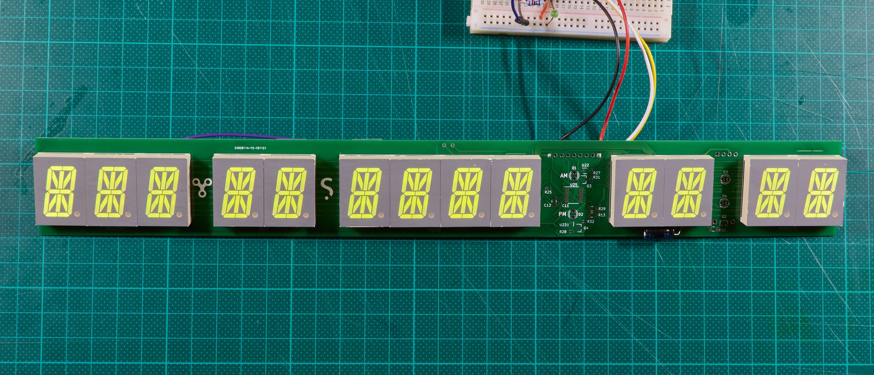
When multiplexing only 7 digits, my original driver is a little dimmer than the HT16K33, but still passable:

When multiplexing 13 digits however, my design is barely bright enough to read, which is the problem the last few project logs have discussed:

The HT16K33 retains the brightness shown here across a full 8 digits per chip, so it's a much better solution for this project. It won't be pretty having two dead-bugged chips on the board, but it will at least make this a functional display for use in daylight.
Hacking in the new drivers
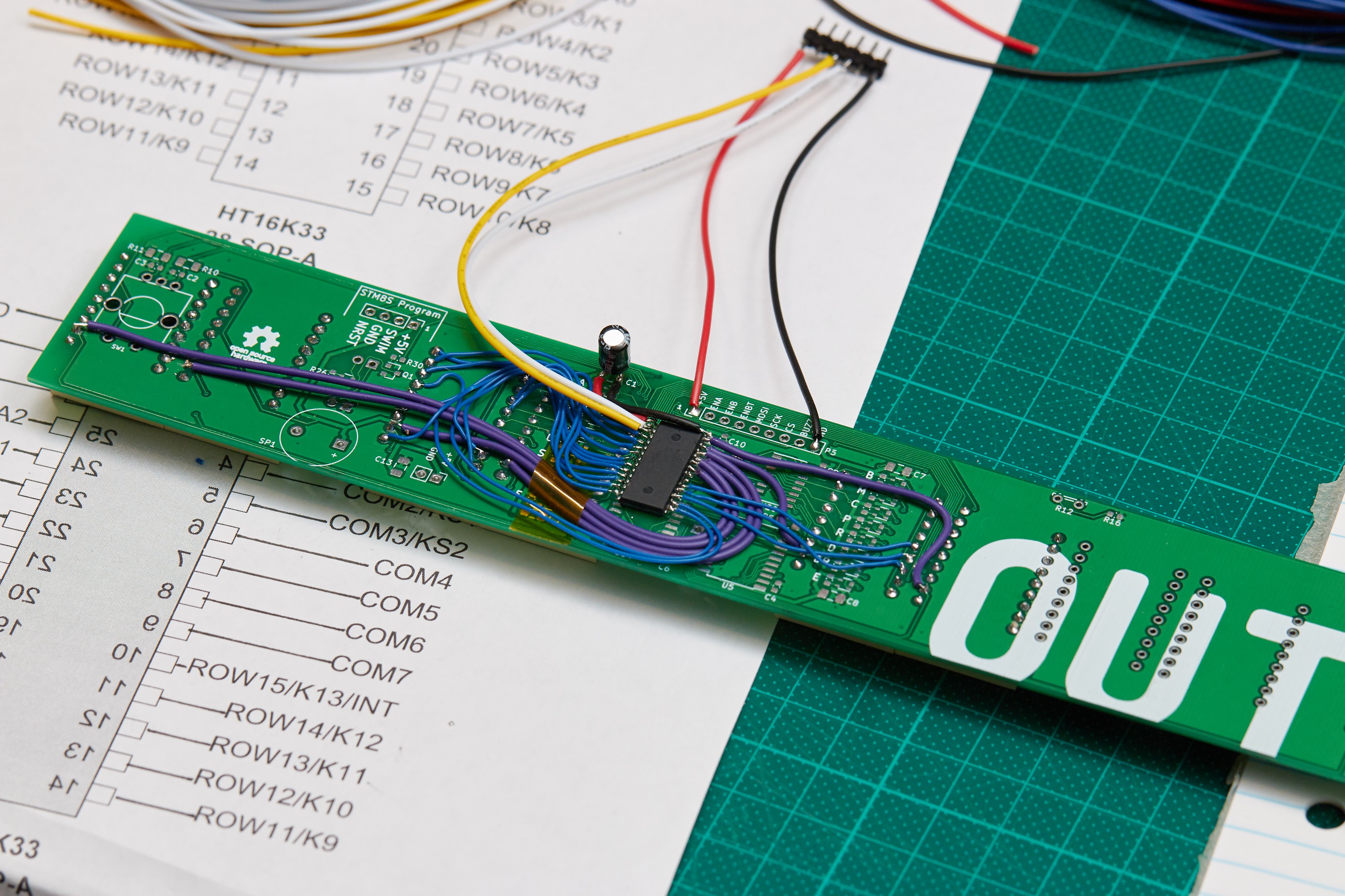
Each HT16K33 is attached to the PCB dead-bug style with double-sided tape, then 26 point-to-point connections need to be made per chip. To help with wiring upside-down, I copied the pinout diagram from the datasheet and mirrored it so it matched my view:

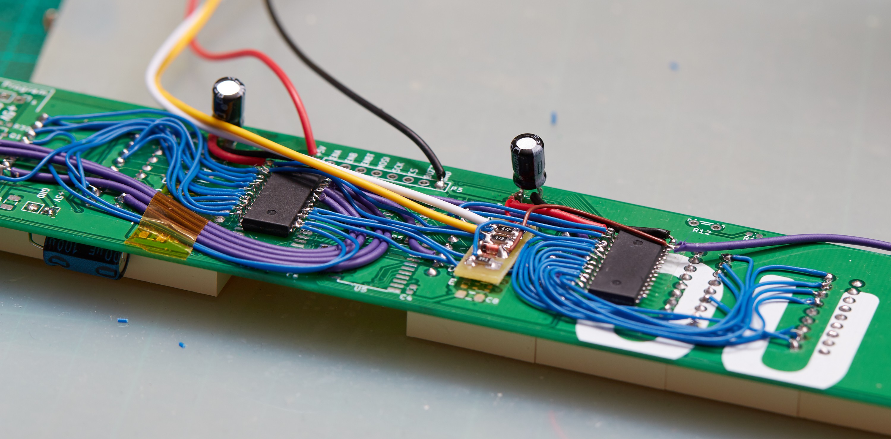
On top of the point-to-point wiring, I needed to fit in two 4.7K pull-up resistors for the I2C bus, plus a diode and resistor to set the I2C address on one of the chips:

To avoid a tangled mess of through-hole components, I hand-drew a little mask for a circuit with 1206 size components and etched that. This was fairly quick as getting a good copper mask using a photo-resist tends to be the most time consuming part of making boards at home:

With all of that in place, this rather extensive bodge is complete:
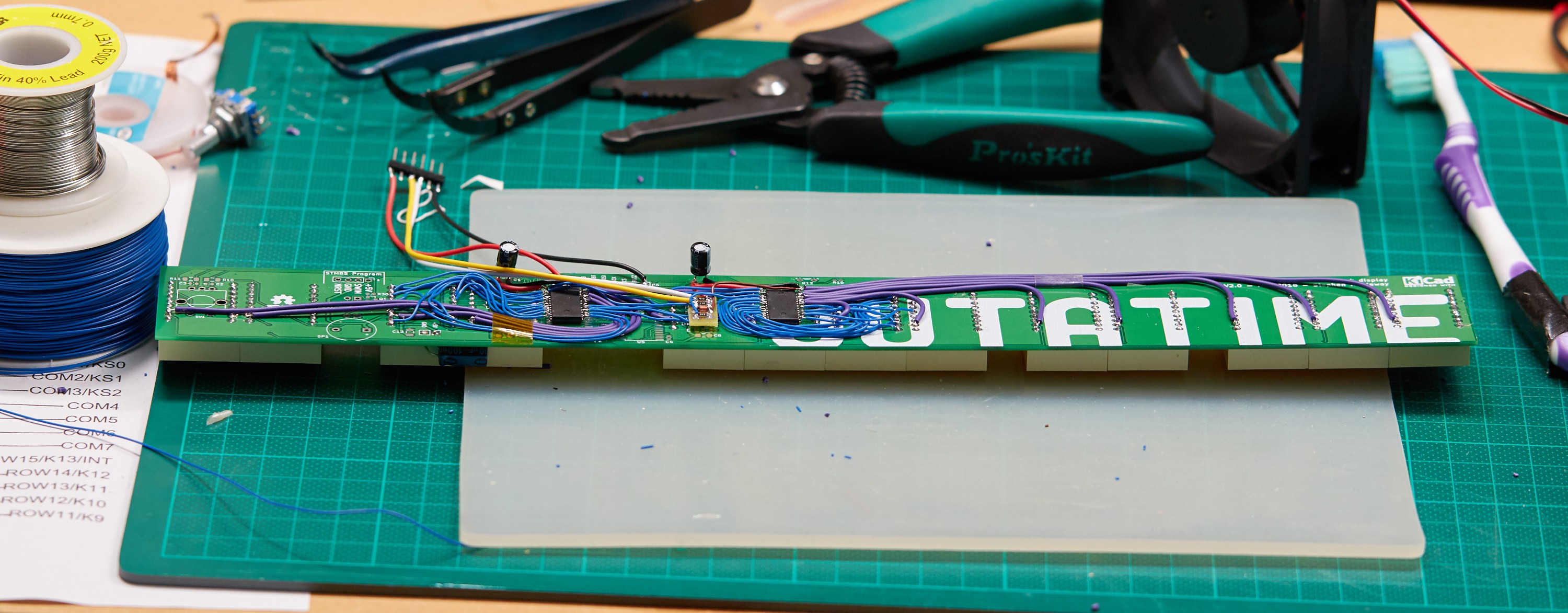
Next up: completing the firmware to use this display as a clock. I won't leave this running all of the time as I already have a few clock projects running in my small apartment, but it'll make a nice show-piece.
Discussions
Become a Hackaday.io Member
Create an account to leave a comment. Already have an account? Log In.
I started developing a driver circuit for the green 4 digit 17 segment LED displays at Electronics Goldmine: https://www.goldmine-elec-products.com/prodinfo.asp?number=G21553 They are cheap, but it turns out that common anode is quite challenging to drive. HT16K33 outputs have to be reversed, meaning lots of extra components. I developed a schematic, but have not completed or built it. Link to ZIP containing Kicad schematic below.
Are you sure? yes | no
http://www.synthify.com/39477281/685425/12390487/Green14segLED%20%20(Partially%20Complete).zip
Are you sure? yes | no