 agp.cooper
What a can of worms!
The mixing of analog and digital can get very messy. I spent the day transposing the lead-lag low pass filter into digital via the z-transform. I think the coefficients model the filter but how to be sure? The coefficients however are not that integer friendly.
The Wiki PLL uses a "Proportional and Derivative" concept that basically equates to a variable gain one pole low pass.
The Wiki PLL page discusses the problem with a simple RC filter, that independent control of damping factor and natural (i.e. damping) frequency is not possible:
- wn = ((KpKv)/(RC))^0.5
- d = ((KpKv)*(RC))^-0.5
For critical damping (d=0.7071):
- RC = 1/(2*KpKv)
Therefore (the low pass corner frequency) should be:
- wc = 1.414*KpKv !!!
The reason for pursuing the lead-lag filter is that the low pass corner frequency and the damping factor can be separated:
- wc = (R1+R2)*C
- wn = ((KpKv)*wc)^0.5
- d = wn*(R2*C+1/(KpKv))/2
- = wn*R2*C as 1/(KpKv) is small.
Neat.
What is not said is that we can easily change the K (i.e. KpKv) of the PLL. This is what I did to get rid of the overshoot. We still need a minimum K to ensure capture and lock of the signal.
The digital maths here is much like a Proportional-Integral-Derivative (PID) control. So more research required.
The 565 PLL FSK Modem
I was looking for some example FSK PLL circuits to analysis (surprising few with component values). I have seen this image many times:
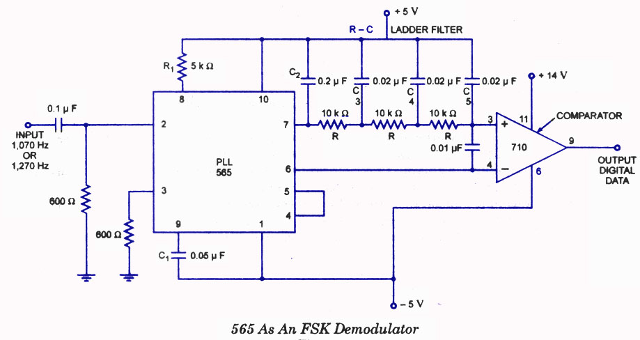
Checking the datasheet:
- Fo = 1170 Hz
- Fl = +/-936 Hz
- KpKv = 3931
For a simple RC LPF:
- Fc = 885 Hz
- Fn = 744 Hz
- d = 0.59
It is clear the designer wanted near critical damping and had no choice but the accept the LPF corner frequency of 885 Hz. In order to compensate the designer used a three stage low pass filter on the demodulated output.
Why did the designer not use a lead-lag filter:
- R1:
- Rinternal 3k6
- Rextrernal 2k2
- R2 15k
- C 0.05uF (no change)
- Fc = 153 Hz (good for 300 baud)
- Fn = 309 Hz
- d = 0.73
I have noticed that others (more recent) have used a low pass capacitor of 0.15 uF which results in:
- Fc = 295Hz (good for 300 baud)
- Fn = 429 Hz
- d = 0.34
Although the low pass filter is better the damping is probably too low.
Designing the Loop Response
Analog Domain
In the analog domain the process seems to be:
- select a damping factor (d) between 0.5 and 1.0 (minimise overshoot)
- select the minimum natural frequency (wn) that meets:
- lock time ~2*pi/wn
- lock/capture range ~2*d*wn
- use lead-lag filters to customise d and wn
I did not have success using a two stage single pole low pass filters.
Digital Domain
In the digital domain the "filter" of choice is PID (Proportional, Integral and Derivative), actually just Proportional and Integral. Here we select wn and d and determine Kp and Ki (the factor for proportional and integral):
- T1 = 1 / WN / WN
- T2 = 2 * D / WN
- B0 = (1 + 1 / Tan(1 / (2 * T2 * SR))) / (2 * T1 * SR)
- B1 = (1 - 1 / Tan(1 / (2 * T2 * SR))) / (2 * T1 * SR)
- Kp = B0
- Ki = B0 + B1
Where:
- WN is the natural frequency
- D is the damping factor
- SR is the sample rate
- T0, T1, B0 and B1 are temporary variable
A first order discrete equation is:
- PD1 = PD0
- PD0 = PD
- LP = Kp * PD0 + (Ki + Kp) * PD1 - LP
Results
Both work but the sinple low pass filter worked better in my case.
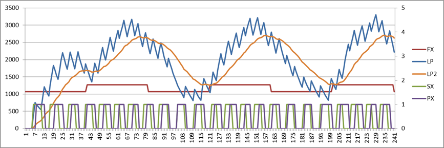
Here is the simple LP filter version:
And here is the PID version:
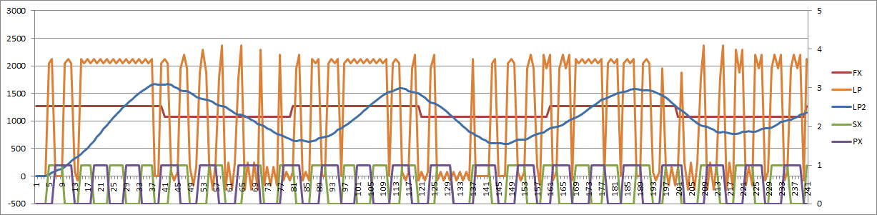
The PID output is the orange (LP) curve. Not sure that the PID control signal should swing from limit to limit.
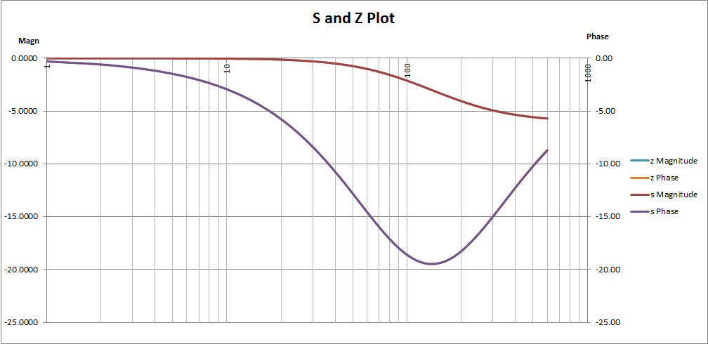
Plotting S Domain and Z Domain Functions
I have not looked at Laplace equations for 30 years and I am not an electrical/electonics engineer so it was a bit of "going back to school". Anyway, worked it out:
- Magn = |F(s)|
- Phase = arctan(Imaginary/Real)
I also worked out how to do the Z domain thanks to:
I have also worked out how to build discrete active filters thanks to:
Why it took a week or more to find this webpage I do not understand!
Here is an s and z domain plot for a simple lead-lag filter (in this case R1=8k2, R2=8k2 and C=50nF):
So I have all the tolls I need for a digital PLL.
AlanX
Discussions
Become a Hackaday.io Member
Create an account to leave a comment. Already have an account? Log In.