 Chris Johnson
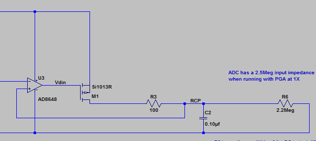
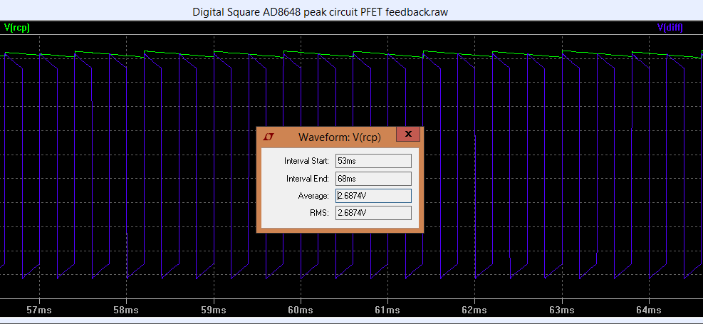
I recently revisited the peak detect issues after a long break working on other projects. I was still dissatisfied with the accuracy of the peak detect circuit. I spent an evening playing around with LTSpice trying various tweaks to make it work more reliably and accurately. The problem with using diodes in a peak detect circuit is that the voltage drop across them is current dependent. I ran in to the issue that the diode in the op amp feedback loop had a larger voltage drop than the diode in the output path, so I was getting an offset is the measured peak amplitude. I knew about the the technique of creating a "perfect diode" using MOSFETs and hit upon the idea of using a MOSFET in the output. The resulting circuit is shown below. In simulation, it works REALLY well. The actual peak voltage is about 2.6878V and the peak detected average is 2.6874V, as shown in the plot below. The ADC measures the average value, since it has a built in low pass filter with a cut off frequency far below the square wave frequency.
The signal to be peak detected comes in on the negative input of the op amp. When the negative input is below the RC low passed (RCP) voltage, the op amp output is driven to the 5V rail, the PFET is turned off, and the voltage on C2 slowly fades due to the 2.2M load from the ADC input. When the negative input is above the RCP voltage, the op amp drives the PFET gate low which charges C2. When the voltage at C2 exceeds the input voltage, the op amp drives the gate back high. The net result is that the voltage at RCP tracks the positive peak of the input. With a repetitive signal like the EC response to a square wave signal, the output is a very good approximation to the peak of the input square wave.
Note that the accuracy of the result depends of the relationships between the speed of the op amp, the PFET, the RC time constants, and the ADC load. A high speed op amp and PFET give better results, since the PFET turns off more quickly when the peak voltage exceeds the input voltage. A low threshold on the PFET also helps by reducing the turn on delay due to the op amp output slew rate. The Si1013R PFET is low cost, low resistance, low threshold, and relatively fast. I have some parts on order and hope to breadboard a test circuit next weekend.
Earlier in the development process, despite all of the searches that I did on peak detect circuits, all I came up with were diode based ones. With this circuit, I thought that I had come up with something new. Of course searching for "peak detect mosfet", you come up with a nice reference about MOSFET based peak detectors (Analog CMOS peak detect and hold circuits. Part 1. Analysis of the classical configuration). Note the "classical configuration" description. It seems that I reinvented the wheel. But it's still a nice wheel. Hopefully it rolls as well in real life as it does in simulation.
By the way, if there is anyone actually reading these log entries, don't hesitate to post in the discussion area with any questions, comments, corrections, or even constructive criticism. How's that for some amazing, astounding, awesome, astonishingly awful alliteration?
Discussions
Become a Hackaday.io Member
Create an account to leave a comment. Already have an account? Log In.