 Chris Johnson
As you can see below, I am breadboarding the new peak detector changes before committing to a new PC board. One of the changes involves using a MAX5387 digital potentiometer to control the square wave amplitude and EC amplifier gain. The new design uses the Raspberry PI to generate the square waves instead of an op amp square wave oscillator. These updates allow you to have square waves with software programmable frequency and amplitude. The op amp that was used as a square wave oscillator is instead used as a comparator to convert the 3.3V GPIO square wave into a full scale 5V square wave. Half of the MAX5387 is used to attenuate the 5V square wave before driving the EC gain stage input. The other half is used to control the EC amplifier gain.
For very high conductivity solutions, you need a small amplitude square wave, because the small EC resistance causes a large amplifier gain. For maximum accuracy, you want to make sure that the amplified square wave at the output of the EC amplifier does not get too close to the supply rails, so you minimize the square wave amplitude and EC amplifier gain to keep the output within range. The EC amplifier gain depends on the feedback resistor and the EC resistance seen by the probe in the solution.
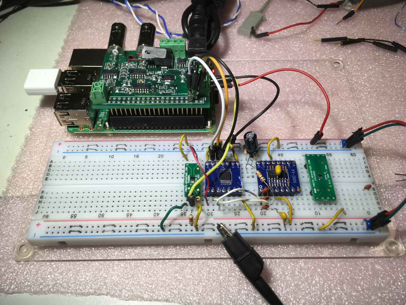 After wiring up the test circuit and figuring out how to get programmable frequency square waves out of the RPI, I started testing the digital pot and ran into the anomalous glitch shown below.
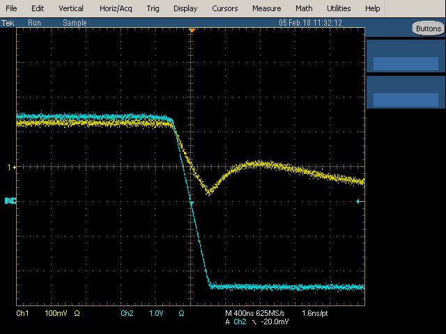 The blue trace is the 5V 12V/uS edge rate square wave from the comparator op amp output. It drives one end of the MAX5387 and the other end is connected to GND. The yellow trace is the wiper output with the MAX5387 set to divide the 5V amplitude down to about 200mv It took a while to figure out that the glitch is likely caused by capacitive feedthrough. There must be a small end-to-wiper series capacitance that allows the square wave edge to feed through to the wiper output. The wiper drives the input to the EC amplifier, so the feedthrough causes a glitch in the edges of the square wave at the output. The output glitch causes an incorrect peak voltage measurement and thus an incorrect EC measurement.
 I haven't decided how to fix this yet. One possibility is to slow down the input square wave edge so that it does not have enough high frequency content to feed through. The other is to find a better digital pot. I think I might go with a different digital pot, since I found the Analog Devices AD5258. It has the unique feature that it is factory calibrated to 0.1% and the calibration is stored in the on chip EEPROM. The RPI can read the tolerance value and accurately calculate the full scale resistance of the pot. Typical resistance values can vary +/-30%. The stored tolerance allows the RPI to accurately determine the actual programmed feedback resistance. The other advantage of the pot is that it has much higher bandwidth than other digital pots. That may reduce feedthrough. The only down sides are that it only has a single pot per package and it only has 64 taps. It also comes in an MSOP package with 0.5mm spaced pins, which are a real pain to solder. I will be ordering some to see if they can help get me out of a glitchy situation.
Discussions
Become a Hackaday.io Member
Create an account to leave a comment. Already have an account? Log In.