 Thomas Flayols
There are plenty of ways to remote control a light for home automation, but most of them are rather expensive and do modify the way you use your switches. Indeed, they replace existing switches or are in series with them like smart bulbs.
A smart switch needs to be powered (often with main), but neutral is not always available in switch box, and on the lamp side, you depend on the existing switch state.
This project proposes to add a relay in your existing switch cases that act as an additional switch. Turning a single switch into 3way; and a 3way into a 4...
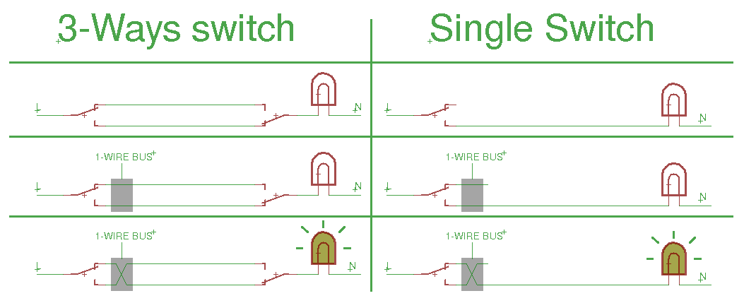
This solution has the advantage to be compatible with every setup I can think of, at the conditions that you have some space in your switch boxes, and that you can add small wires for communication and low DC power.
In most cases, you have some space in existing tubes to put those wires. (This point need some safety attention though)
Then those wires are meshed from all remote switches to a central master controller like a PI, an ESP8266, an arduino, an USB to OneWire converter...
An other good point is that it is transparent if communication or power fails.
Now the problems !
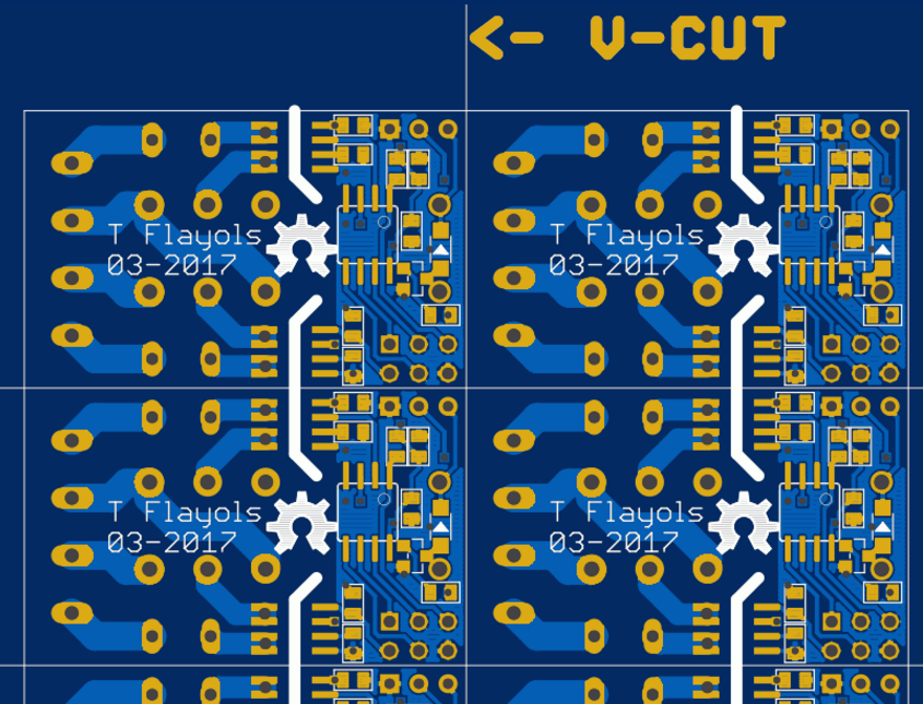
- It has to be super small !
- The module has no way to know if the lamp is ON or OFF since it depends on other real switches.
- Solution: Measure current (it adds cool features to a smart switch)
- Problem : The current can take tow different paths
- Solution: put two sensors and sum the measurements
- Problem : The current can take tow different paths
- Solution: Measure current (it adds cool features to a smart switch)
- For that size, the relays and sensors could allow less current than your circuit-breaker does
- Solution: put a rated fuse on the board
- Problem: the current can take two different paths
- Solution: put two fuses
- Communication could be difficult if we follow main AC wires and for long distances
- Some people report no problem with one wire bus. To be confirmed soon.
Hardware
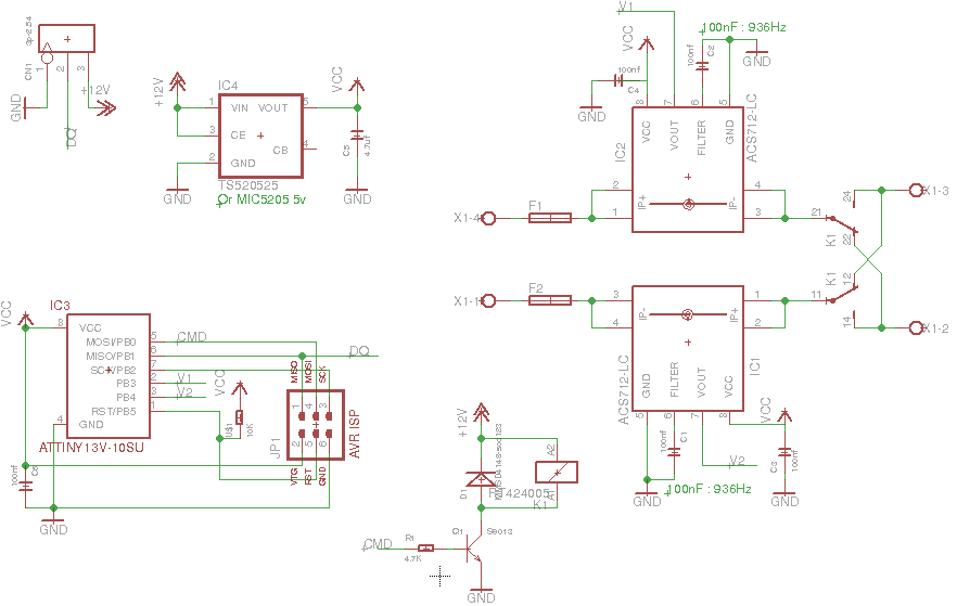
To serve as OneWire slave, and measure current sensor, I chose ATtiny13; It may not be able to do accurate RMS computation, but that should not be a real problem..
Having a uC directly in the switch can provide cool autonomous features, like auto turn off the light after power, acting as timer switch. And we could even imagine extensions like presence detection, temperature sensing...
For the current measurement, hall sensor ACS712 will do. the 5amps version saturates at 5 but can handle more, and isolation is very good for the package size.
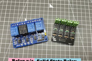
Last important component is the relay. It has to be a DPDT relay for the 4way system. In France we're 25OV guys so it has to tackle it! Also, the coil selection mater. I think a 12v coil is a good solution, the current from Master to Slave is not so high, and the ATtiny and sensor are made insensible to voltage drop using a 5v regulator. A too high coil voltage would mean power losses in 5v regulation.
Software
As Attiny13 is tiny ! I plan to use this arduino core https://github.com/MCUdude/MicroCore
It even allows us to code in true AVR C without arduino lib if needed...
For the OneWire slave lib, I've seen some implementation, not sure yet what to chose.
For RMS computation, I plan to store sum and sum of squares of samples as fast as possible for one electric period, and then do RMS. But maybe I over estimate the ATtiny capabilities...
Registers to implement are a work to come but some idea:
Read registers
- current sensor
- time from last user switch
- lamp fault detection
- ...
Write register
- set lamp state
- toogle lamp state
- cutoff current
- 50/60Hz
- ...
Note
This project can be dangerous... I'm sure some of you have ideas to make it safer,
Please comment !
A GitHub repo is coming soon for both hardware and software.


 ElectroBoy
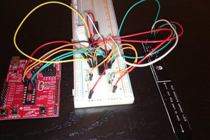
 Michael Haas
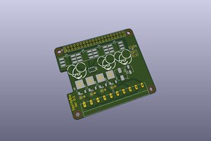
 greenscum
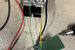
 Will Stone
@Piers Hawksley
The pcb is rated at 250V - 5A for 1oz copper weight. For 2oz, the relay limit us to 8A.