Close
0%
0%

Bruce the Shark

Airswimmer converted to be controlled using a mobile app through WiFi

Similar projects worth following
Airswimmers are helium filled balloons shaped like fish (there is a shark model and a clown fish model). Out of the box, they are controlled by a simple, two channel remote. The idea of this project is to make the airswimmer more controllable and maybe serve as a platform for experiments in autonomy. To this end, propulsion is changed into dual propellers, while the remote control is replaced by a 433 MHz wireless connection, with a base station providing a network accessible interface to control the shark.

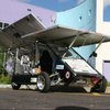
In the original configuration, the airswimmer is propelled by the tail fin, which can be flapped left-to-right using the remote. The whole fish can also be tilted up or down by moving the gondola, which holds the battery and receiver, forward and back along a rail attached to the belly of the fish. This combination of controls allows the user to move the airswimmer around in a fluid motion, which is quite pretty to watch. With some practice it is possible to get fairly accurate control.

My dot-on-the-horizon goal for this project is to build a platform for experiments in autonomous behavior. A balloon is quite an attractive platform for this, since the relatively slow movements make collisions far less dangerous than with, say, a quadcopter. 

The main challenge when working with helium balloons, however, is the limited payload capacity. For this project, my mass budget is about 100 grams for the controller, propulsion AND battery. This was a large driver in the selection of technologies and parts, and led me to select a small, 600 mAh LiPo battery to power the whole thing. 

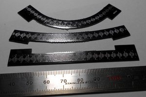
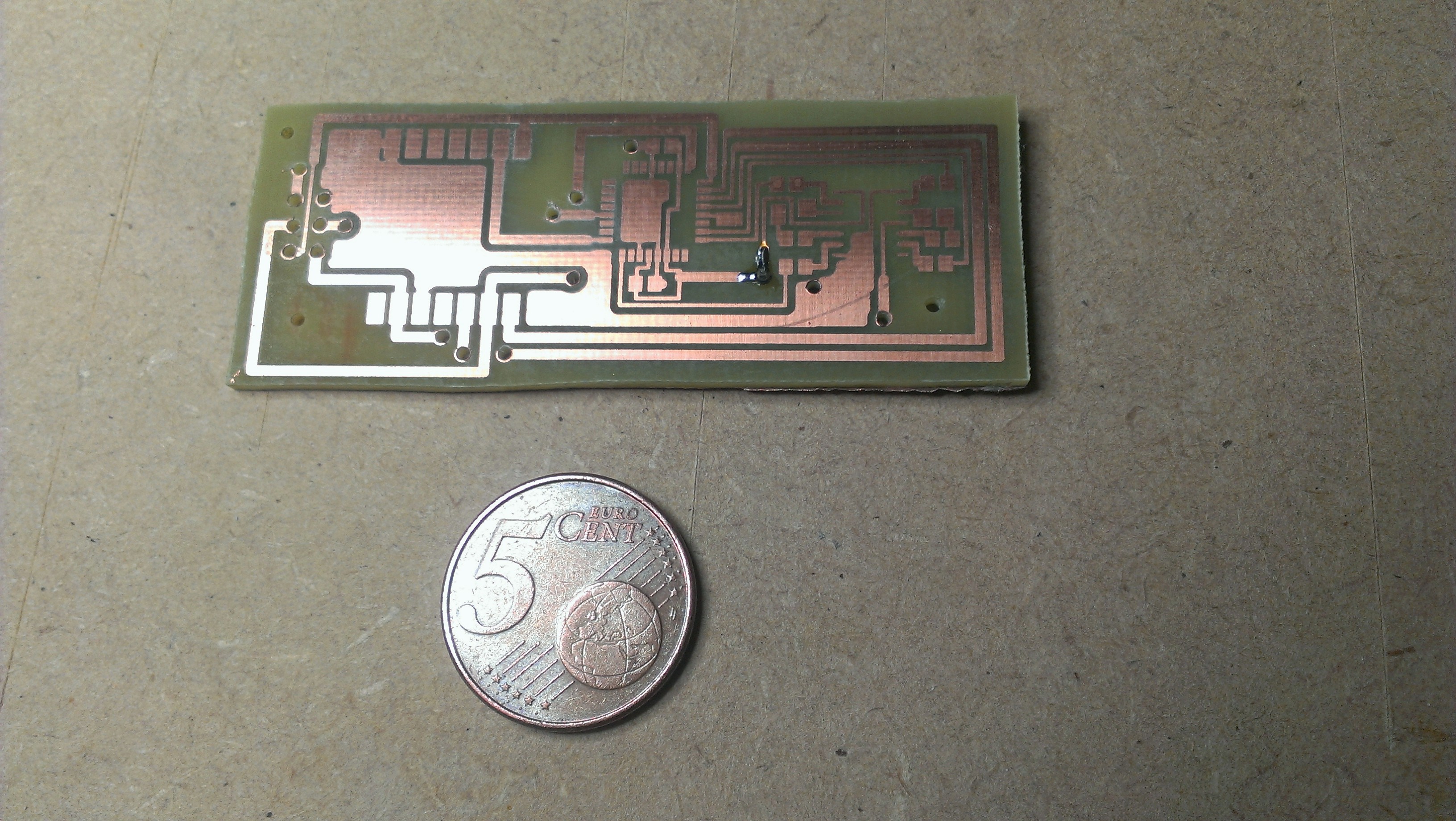
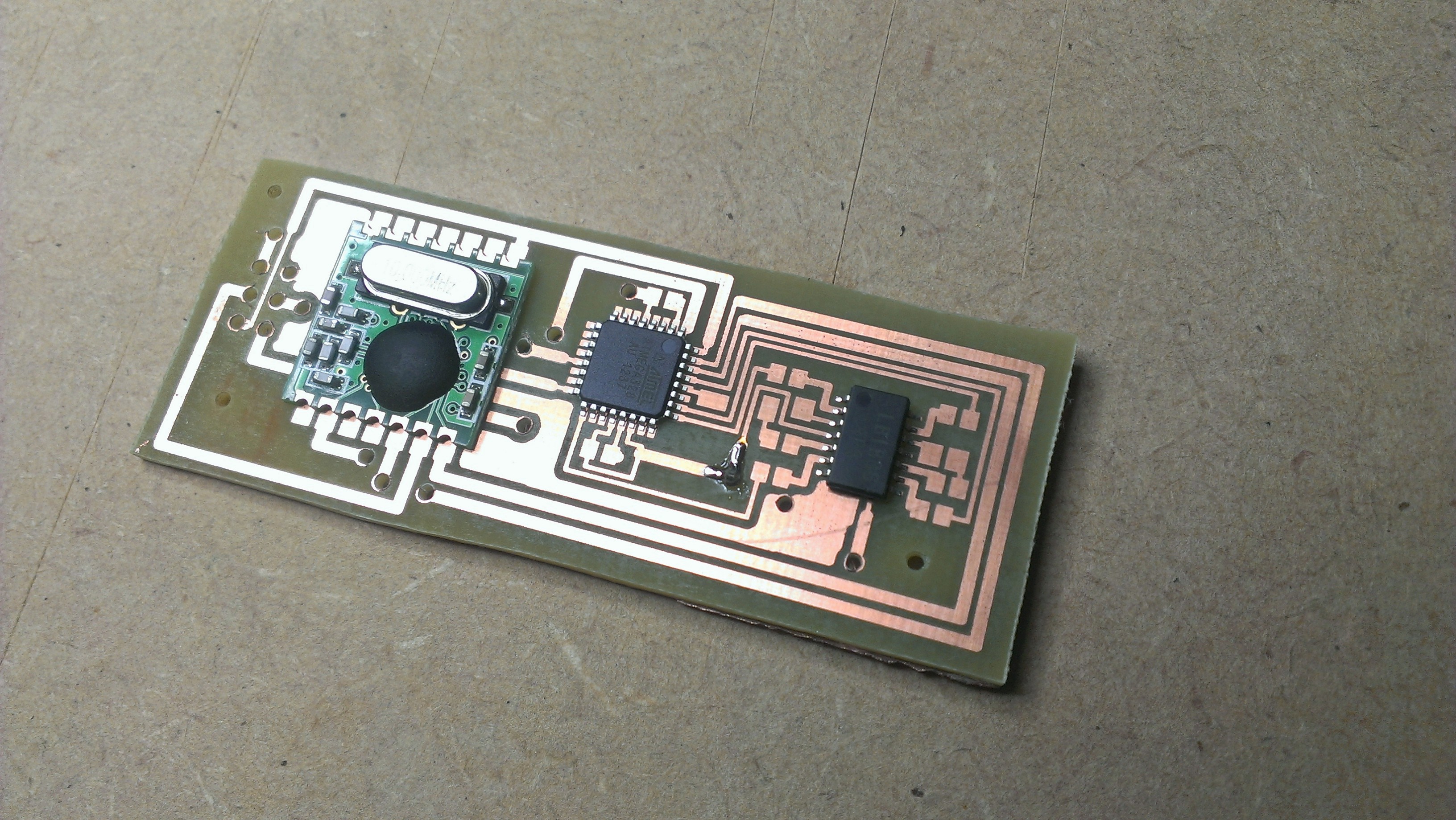
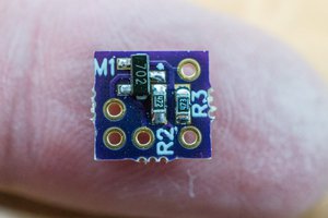
I also wanted to use the Arduino toolchain because of the easy availability of a large selection of libraries, but a standard Arduino is way too big and heavy. So I decided to develop my own, minimalist board, which ended up holding only 11 components: 6 resistors, 2 capacitors, an RF12B 433 MHz module, an Atmega328 microcontroller and a LB1836M motor driver IC. The PCB is designed in EagleCAD and produced using the UV-exposure method.

The firmware running on the on on-board controller is pretty simple. It simply sits there, waiting for messages to come in through the wireless connection. It handles simple commands indicating which PWM pin should be set to which value. The protocol can be expanded to include control of digital pins and even reading analog values (which can then be reported back to the ground station), but the current implementation does not support this.

When stripping down the airswimmer, I discovered the tail fin and gondola are moved by two identical small DC motors. I decided to repurpose them to directly drive a couple of small propellers. While the shaft-diameter is a not a common size, I was able to source a small supply of  50 mm props that had the right size hole. The motors are rigidly connected to each other, and can be tilted up or down by a servo. 

The ground station is a Nanode, which is an Arduino clone which replaces the USB connector of the original with a standard ethernet port and a Hope RF12B wireless module. The nanode provides a REST-API to control the shark, meaning requests take the form:

http://192.168.0.101/1/pins/[motorid]?value=[0-100]

where [motorid] is either lprop, rprop or servo, and value can be anything from 0 to 100. With the prop motors, this value indicates their PWM percentage. With the tilt-servo the value indicates the position within the full allowed range.

  • 1 × Atmel atmega328P TQFP The well-known microcontroller used in the Arduino (8-bit AVR architecture)
  • 1 × Hope RF12B 433 MHz wireles transceiver
  • 1 × Sanyo LB1836M The LB1836M is a low-saturation two-channel bidirectional motor driver IC for use in low-voltage applications.

  • PCB fabricated

    Jeroen03/15/2014 at 22:50 0 comments

    So the PCB fabrication worked out nicely. I recently switched from using the toner transfer method of home fabricating PCB's to the UV exposure method because I wanted to make compact boards with small SMD components. My experience with toner transfer indicated that while this may be possible to achieve using that technique, it will be pretty hard to get reliable and decent results. So as a side-project I constructed a small UV exposure box using UV LED's I found on the cheap on aliexpress. 

    Using the double-sided photosensitive PCB's and developer I get from my local electronics supply store (Brigatti), making a PCB is really very easy. I am amazed at how tolerant modern photoresists are against over-exposure. After some experimentation I settled on an exposure time on my 84 LED UV box of 3 minutes, but anything from 2.5 to 8 minutes (the longest I tried) works just fine. Similarly, once exposed and developed, the remaining etch resist is very hardy. I can safely let the board sit in the etchant until all superfluous copper has been removed without loosing even the thinnest traces.

    The end-result looks like this, with a 5-cent coin added for scale reference (and with one via already in place, as I forgot to take a picture at first):

    And here is the same PCB with the main components (wireless module, microcontroller and motor driver IC) laid out. The middle chip is the Atmega328P TQFP package (32 pins)

  • Ready to fabricate

    Jeroen02/26/2014 at 21:09 0 comments

    The current state of the project is that I have a working breadboard ​implementation of the circuit, and all the firmware seems to be working as well. The last week or so I entered the schematic into EagleCAD and designed a PCB based on that. So I am now ready to start fabricating the PCB. I can say with confidence this is the most challending PCB I attempted to create at home yet. When working in the cad software it looks fine, but when I printed the layout (on paper, just to check) I realized it is TINY! Apart from the ISP programmer pinhead, all components are SMD's. The entire PCB is about the size of a stick of gum. I'm glad I made a UV exposure box a while ago. This would have been quite impossible to fabricate with the toner transfer method I used previously. It's a 2-layer PCB as well, although I deliberately made the bottom layer such that it can be easily done using a few wires instead. Here is the final result:

    Hopefully I can show the final product in the next update.

View all 2 project logs

Enjoy this project?

Share

Discussions

dmritard96 wrote 08/21/2014 at 20:08 point
Hi, We were wondering if you had an eagle library for the lb1836 package?

  Are you sure? yes | no

Jeroen wrote 08/22/2014 at 07:06 point
I made an eagle component myself. You can try the schematics on github (https://github.com/jeroen94704/SharkRemote), see if that meets your need. If not, let me know, and I can send you the component separately.

  Are you sure? yes | no

Similar Projects

Does this project spark your interest?

Become a member to follow this project and never miss any updates