 Thatcher Chamberlin
One of the most important parts of my touchscreen device is the analog circuitry that turns the piezo element outputs into digital inputs for the microcontroller. I'm currently using two op-amps configured as comparators to do this. The way these comparators works is simple: if the input voltage is higher than a given control voltage, the output is low. If the input voltage is lower than the control voltage, the output is high. The control voltage is set using a potentiometer called RV1 on the schematic in my first project log. However, since the control voltage that I've found works best detecting pulses from the piezo sensors is so low, I only use about 15 degrees of rotation of the potentiometer out of the available 270. I've decided to add a new resistor in series with the potentiometer to bring its range of output voltages into an area that closer to what I actually want.
Here's a schematic of the potentiometer as I usually have it set:
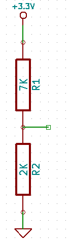
The output voltage of a potentiometer wired in a voltage divider configuration like this one is (v0*R2)/(R1+R2). Here, the output voltage is (3.3V*2000)/9000, or .733V. That's the voltage that I would like my modified voltage divider to have as its highest output voltage possible. Here's a diagram of what I would like that new voltage divider to look like:
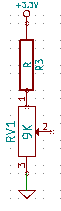
The trick will be to determine the value R of the added resistor R3. Basically, I want R2/(R1+R2) from the first divider to equal RV1/(R3+RV1) from the second divider. Here goes:
R2/(R1+R2) = RV1/(R3+RV1)
R2*(R3+RV1) = RV1*(R1+R2)
R2*R3 + R2*RV1 = RV1*(R1+R2)
R2*R3 = RV1*(R1+R2) - R2*RV1
R3 = (RV1*(R1+R2) - R2*RV1)/R2
R3 = (9K*(7K+2K) - 2K*9K)/2K
R3 = (81K - 18K)/2K
Giving us...
R3 = 31.5K ohms.
We can double check this with the original voltage divider formula.
V = (3.3V*9K)/(31.5K+9K)
V = .733V. Nice! I love it when it works.
The closest resistor I had on hand to 31.5K ohm resistor was a 33K ohm resistor. That gives a .707V output which I think should be close enough.
UPDATE: I added the new resistor and the math proved correct! I measured the output voltage of the voltage divider with the potentiometer turned all the way up (highest possible output voltage) and measured the output at .732V. Even closer than I expected! Anyway, after using my new extra-sensitive voltage divider in some testing, I determined (empirically) that the best control voltage is 0.081V, or 81 mV. I'll add the new resistor to the schematic soon.
Discussions
Become a Hackaday.io Member
Create an account to leave a comment. Already have an account? Log In.