Basim Cheema-Sabir
-
Prototyping w/ 74HC595 Shift Register
04/01/2025 at 22:00 • 0 commentsUnfortunately, I ran into some hiccups with the v4 PCB, and since it mostly involves small SMD components, debugging it proved difficult. Instead, I pivoted to testing some basic shift register logic with a more well document shift register, the 74HC595, with the Arduino Nano. Below is a video of 3x2 braille cell-style array of LEDs flashing through the braille alphabet while being controlled by the shift register.
The Arduino code can be found in braille_flash.ino in the GitHub.Next Steps:
I will try to control an H-bridge IC with the shift register and hopefully be able to control current flow through the coils. Once that works, I will begin designing the v5 PCB implementing these new shift register/h-bridge ICs.
-
v4 Parts + PCB Assembly
03/11/2025 at 07:14 • 2 commentsUpdate 3/11/2025:
Shift Register and H-Bridge ICs arrived, and PCBs arrived. Soldered SMD components on using microscope and fine soldering tip.
![]()
![]()
Next Steps:
Write Arduino code to control shift register and send input signals to H-Bridge ICs.
-
PCB v4 Schematic & Design
12/18/2024 at 03:27 • 0 commentsUpdate 12/17/2024:
Researched different ICs for controlling a full 6-dot braille cell.
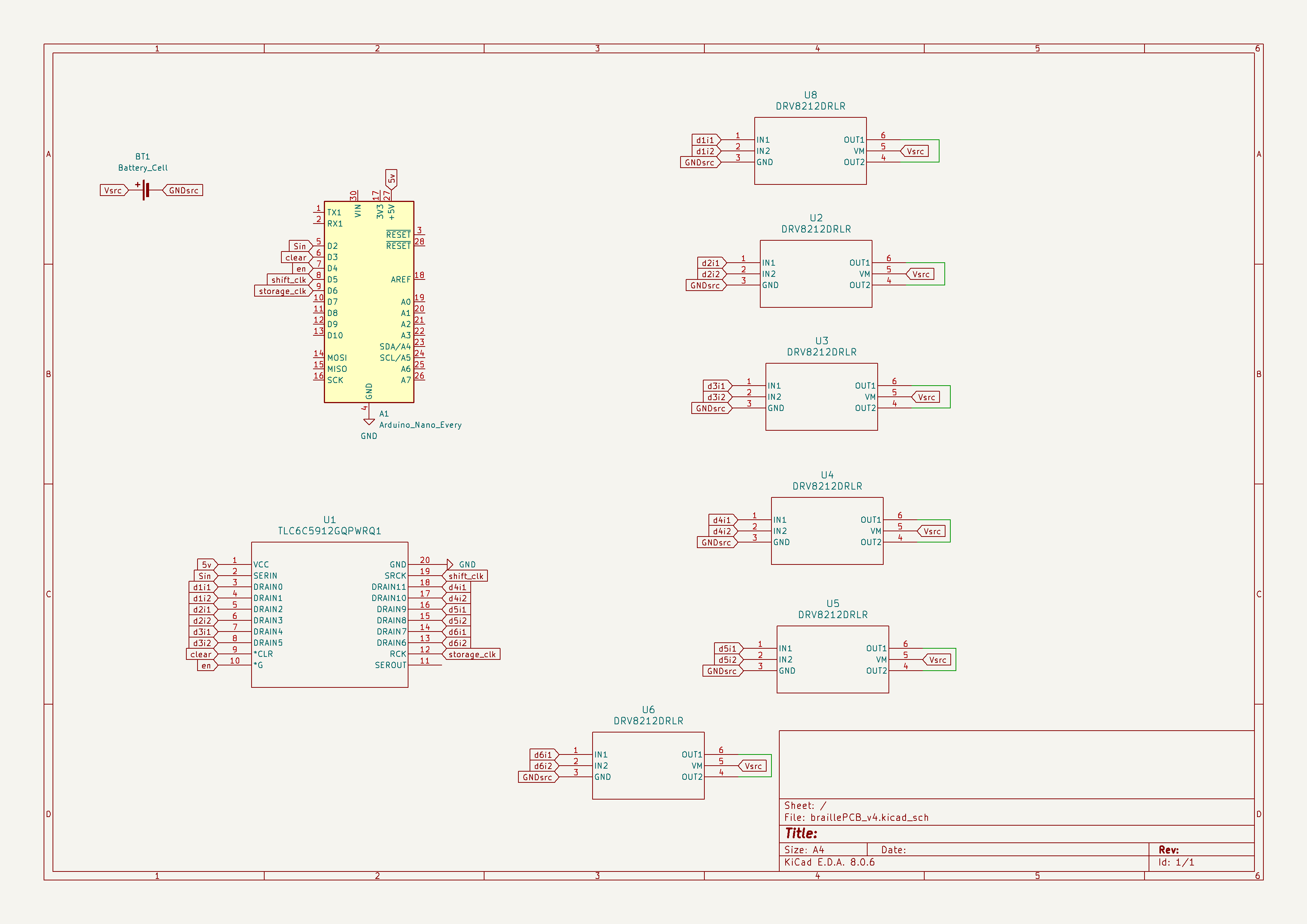
TLC6C5912-Q1 12-bit shift register, to control all 12 outputs associated with the full cell. Two outputs are required for each dot to drive current in both directions.
DRV8212DRLR H-bridge motor driver IC, to take digital signal from shift register and enable current flow in a specified direction.
Completed PCB v4 design:
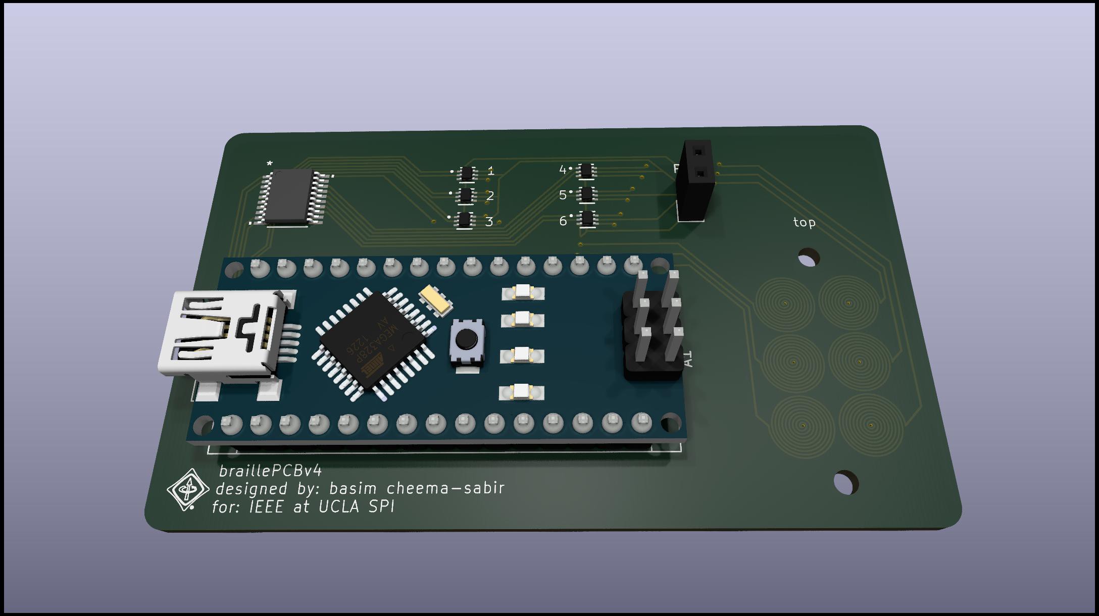
3D render:
![]()
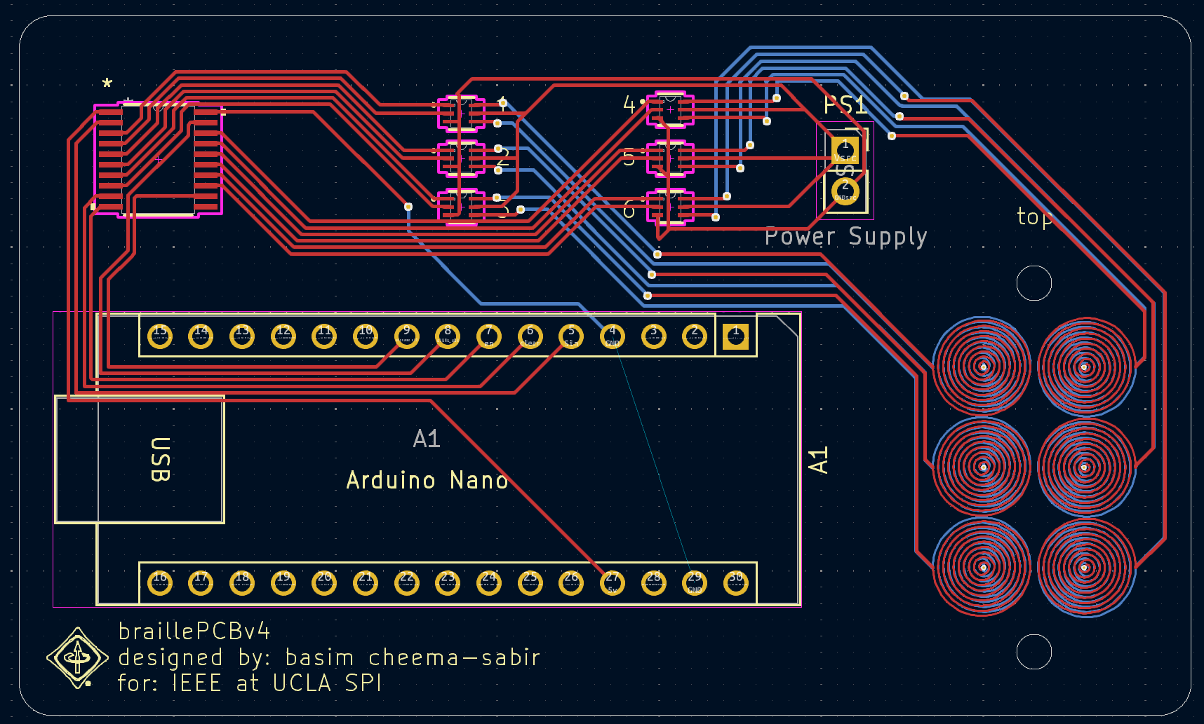
KiCad design:
![]()
Completed PCB v4 Schematic:
(coils not shown)
![]()
-
PCB Arrival, Completed First Prototype + Successful Initial Testing
11/14/2024 at 06:17 • 0 commentsUpdate 11/13/2024:
PCB Arrival
PCBs arrived from JLCPCB (pictured below)
![]()
![]()
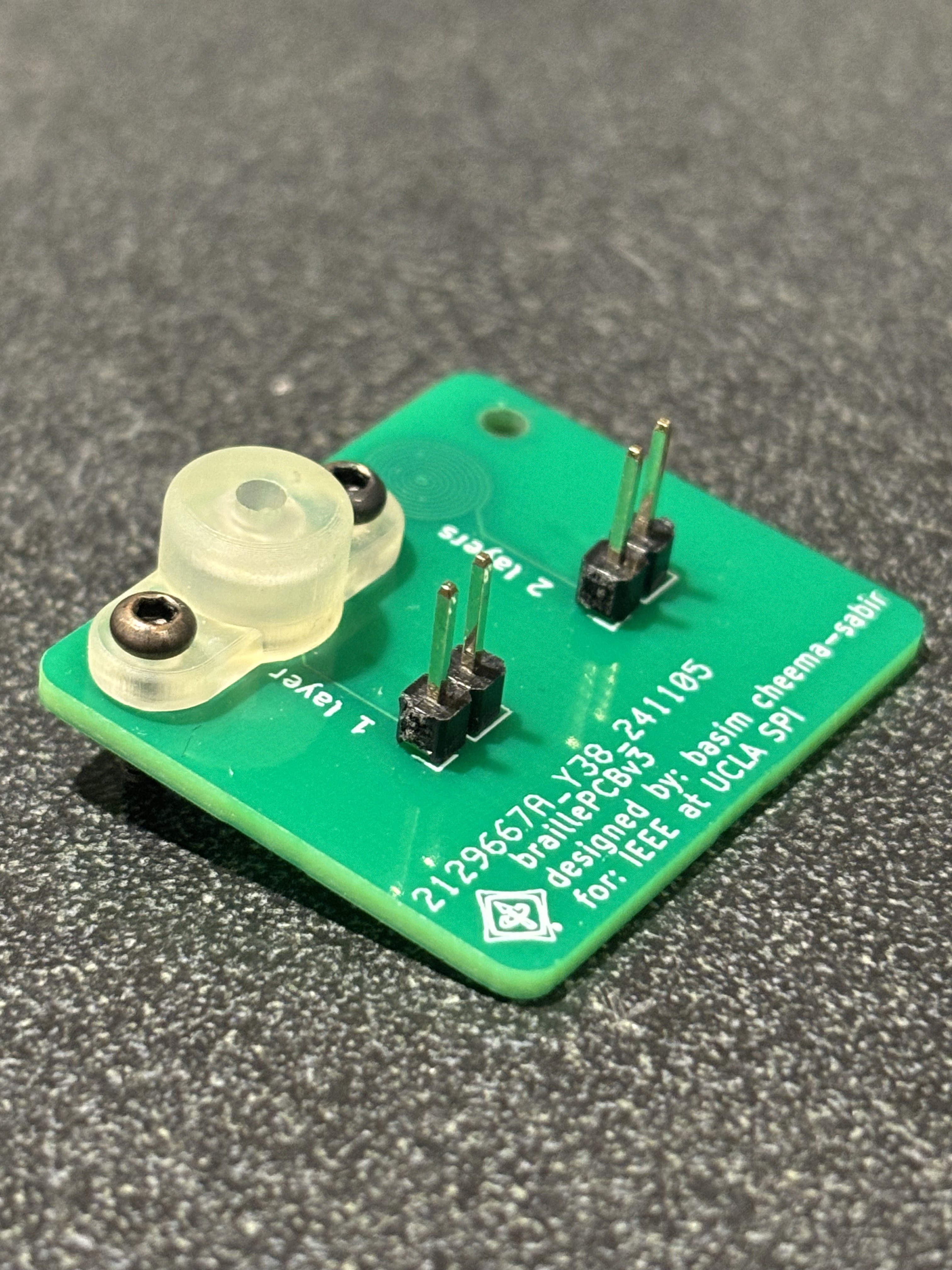
Completion of First Prototype
Soldered pin headers, bolted 3D-printed assembly to PCB
![]()
![]()
Successful Testing
See video
-
Printed first prototype parts, Designed first prototype PCB
11/04/2024 at 21:18 • 0 commentsUpdate 11/04/2024
First prototype PCB design consists of two coil setups, one of which is a single layer, the other being a two layer version, connected in series. Each coil is 6mm in diameter with a 0.15mm trace width/clearance, and approximately 9 turns per layer.
PCB design:
![]()
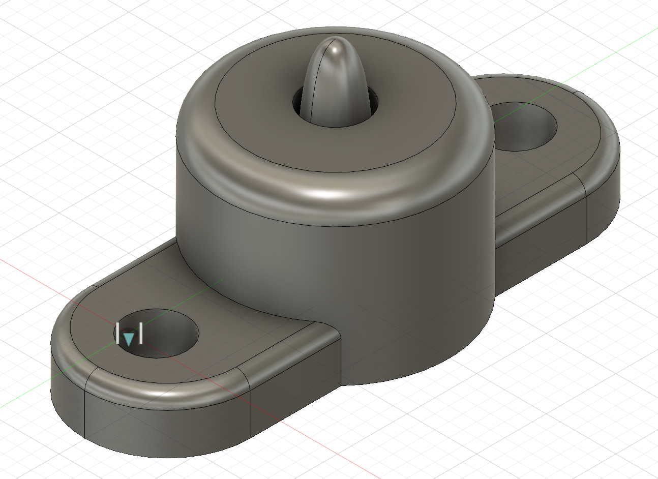
CAD model:
![]()
M2 bolts will be used to align and fasten the outer 'chamber' part over the center of the coil.
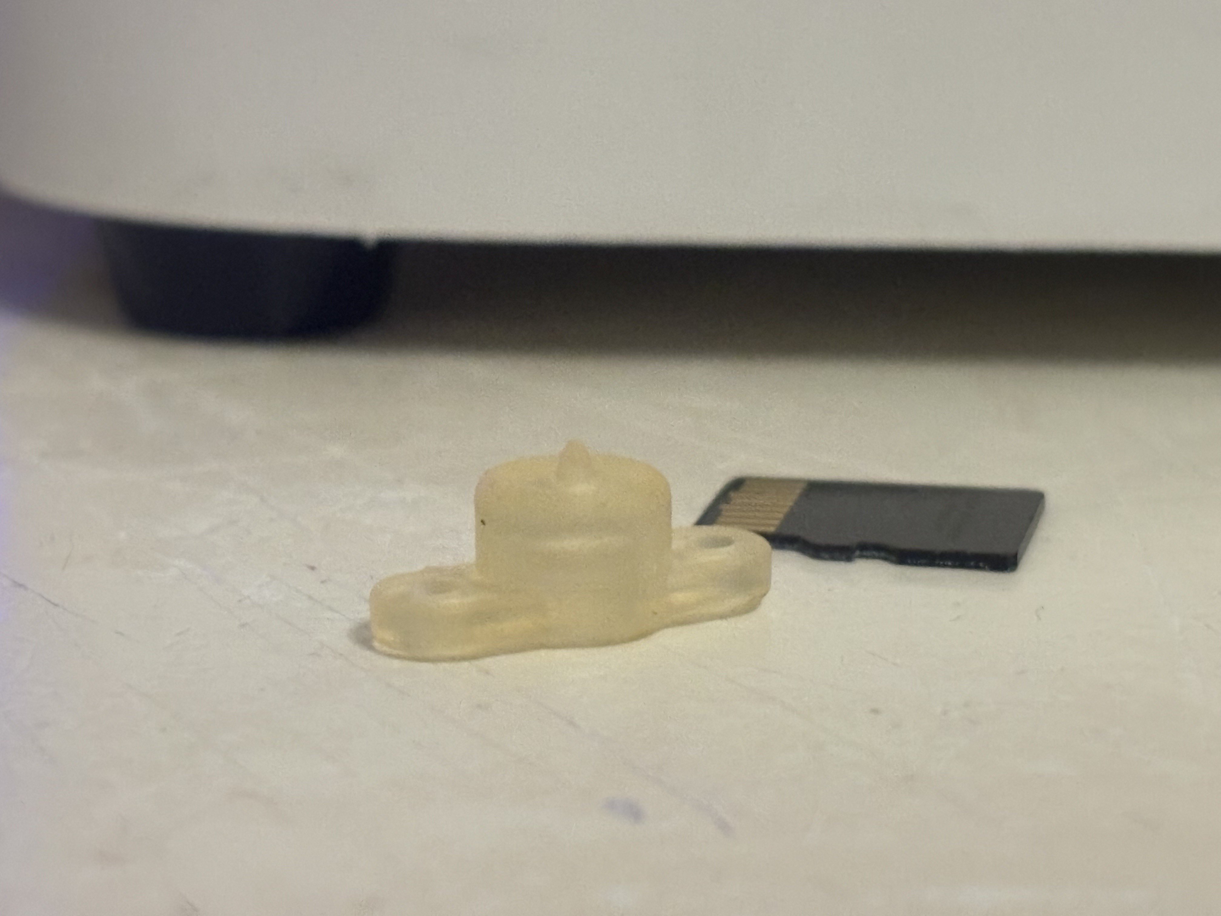
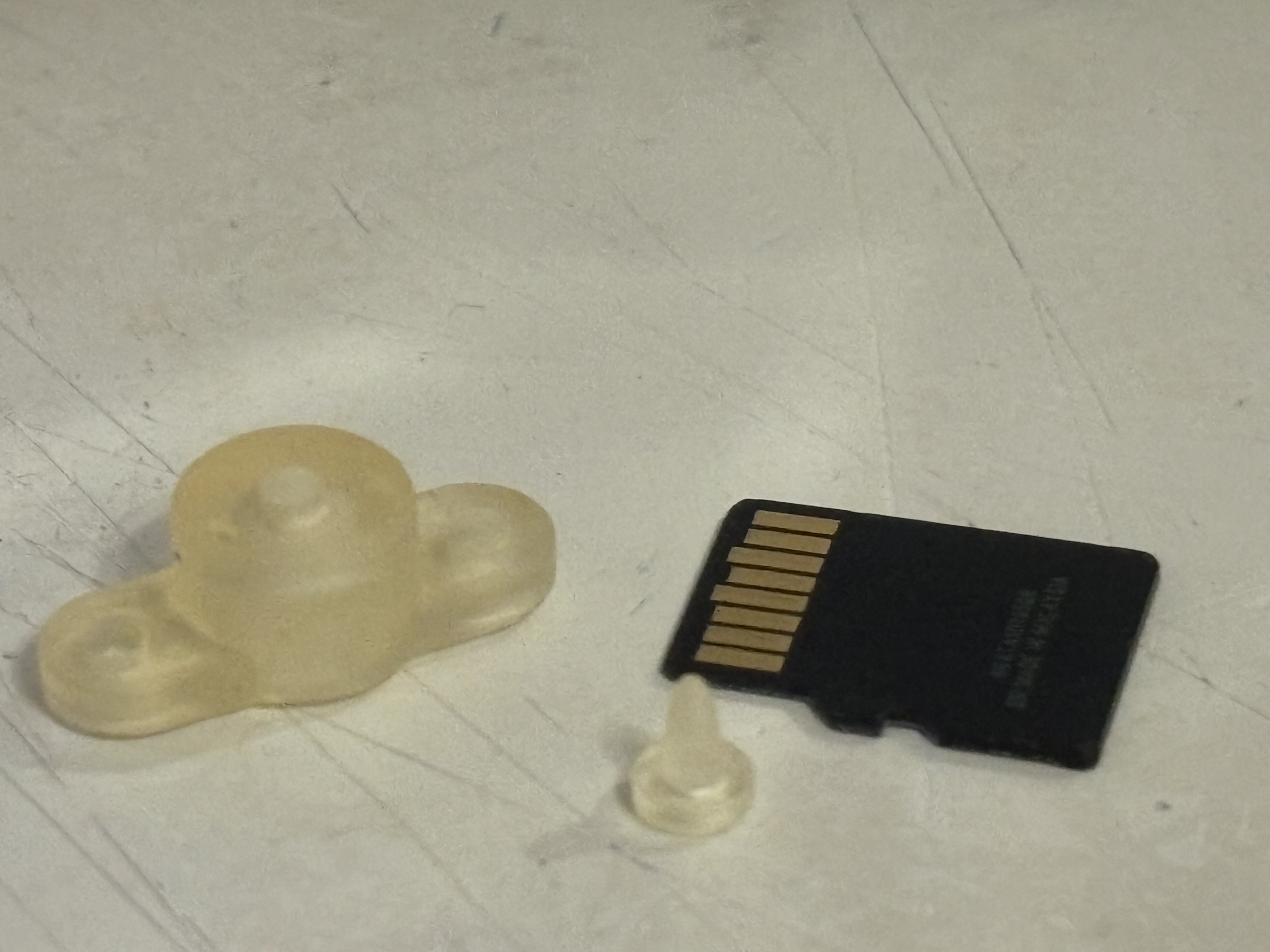
The two parts were printed on the Creality Halot Lite SLA 3D-printer using clear ABS-like resin.
Printed parts (microSD for scale):
![]()
![]()
Refreshable Braille Display
Refreshable Braille Display powered by PCB electromagnets