 Morning.Star
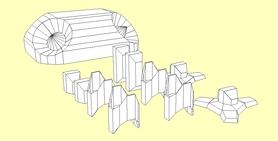
...And populating them
* Now with code to handle multiple objects, save and load objects to a human-readable file and rotate the scene with the cursor keys. This is as about as far as I am taking the Python code as it has served its purpose, to design and assemble the models. There is a bit of tidying up needed, a routine to attach the limbs in a proper chain using the joint angles to display the entire model... And another to export the parts as WaveFront object files, which is pretty easy. Then Cardware can be 3D-printed, milled and rendered in almost any rendering package commercial or otherwise, be simulated in many engines, and, represented by a networked Cardware engine and optionally attached to the sensors on a real Cardware model...
 Most of this code will be rewritten in C++ so I can draw those polygons with my own routines and handle the depth on a per-pixel level. This also means I can wrap a photograph of the real one around it. Python is way too slow for this without a library, and PyGame's polygon routines would still be terrible if they understood 3D coordinates. ;-)
I suppose I have to make that skins editor I toyed with while printing the plans now, to make that easy. Double-sided prints are possible but are a bit of a pain to line up properly and I dont have cash for colour cartridges laying around, or at least some of my Metal Minister would have been photographic. Using a skins editor can make that simple, and it isnt just for pretty although that is a consideration;
The main reason is to map the robot's markings to its geometry so it is recognisable to another. Because they are a shared system this information is available to all robots in the network so they can say this is where I am and this is what I look like, so the visual recognition system can verify it and link it to the world math. But, it doesnt have to be a real robot, it can equally be a simulation which the individual robot's 'mind' wont be aware of. Even the simulated ones...
We beep, therefore we are. :-D
To understand the world, and indeed itself, a robot needs to metricate everything and represent it mathematically. It is very important for movement that the robot also understands its perimeters and not just the angles of the joints, so it has situational awareness. So, the first thing I had to do was measure everything and create mathematical models for it to represent itself with.
First the easy bits, simple to pull measurements directly off the plans in MM. I'm using that because it fits better into denary math and I can round it to the nearest MM without affecting the shape. The card itself has a 0.5MM width and the physical model can vary by that anyway.
Turns out the model can deviate quite a lot from the plans even when they are printed and folded to make the actual model, and accuracy has little to do with it in practice on some parts. More on that later...
The Thigh Module
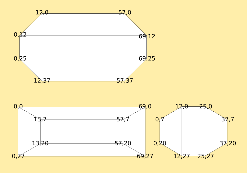
Hip and Ankle Modules are simply half of the above part, easy to generate a mesh for during import. The legendary Hip Unit (Units are unpowered, Modules are powered) was already measured to calculate the inner radius from the outer, a 2mm difference in diameter.
The Hip Unit
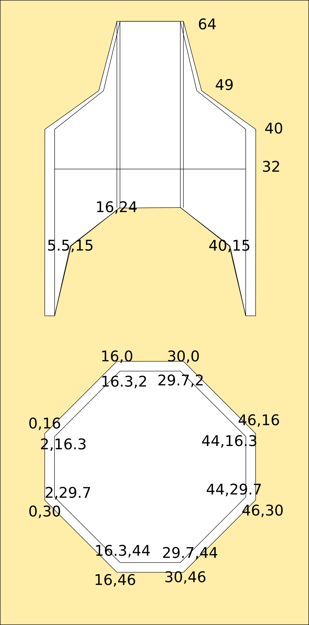
The foot is more complicated. Filled curved shapes are a nightmare to compute edges for, so I've broken them into a mesh. This was done manually in Inkscape from the original drawing.
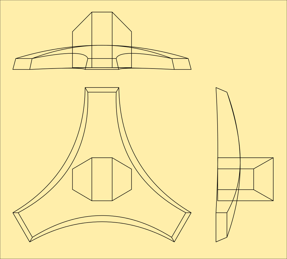
Overlaid with polygons and then measured, thats the foot done too.
The Foot Module
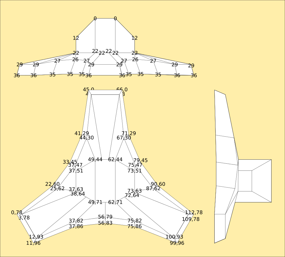
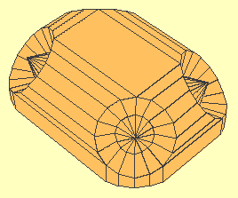
The lid was a little bit more complicated. While I can draw orthogonal plans to scale I'm not entirely sure thats accurate to the MM in all three dimensions. The original MorningStar was not calculated to be the shape it was, I discovered the fold almost accidentally and then figured out the mathematics for it, then used them to compute the lid dimensions as curves. Interpolations from that math was used to create the mesh visually, but is it correct? I dont know for sure.
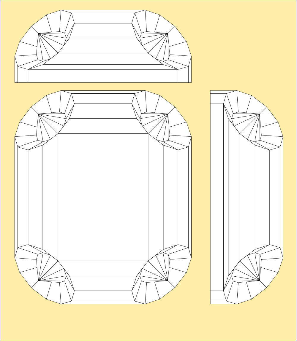
It looks pretty close, but it isnt exact. I recreated the mesh in Python from the given dimensions so I know its accurate. Each corner is defined as 33 points in two concentric circles surrounding a centre point. Then the edges of the circles are joined with polygons.
That just defines the vertices and the edges joining them as a list of XYZ coordinates followed by a list of groups of four pointers into it. Once this information is obtained, its fairly easy to rotate them into any position.
This is still not the end of the story, the computer still doesnt understand 3 dimensions fully although it knows about them. It has to be instructed that the further away from the screen the coordinate is, the smaller it appears - this is perspective projection, and its important because when the robot sees with its camera, the world will be distorted by it and will need correcting for orthogonal projection inside the map.
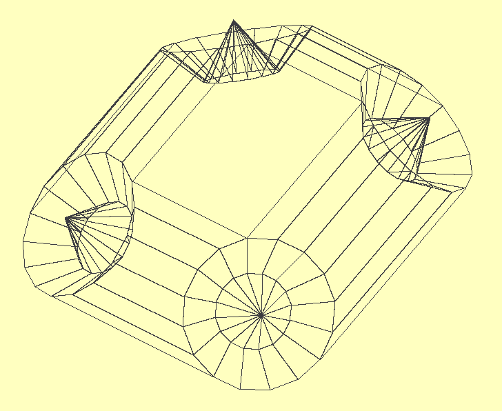
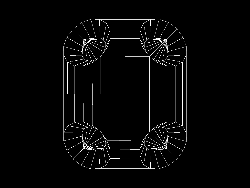
It also needs to be told that objects can be in front of other objects and thus obscure them, so the system caters for depth by sorting everything it 'sees' into order and working from the back to the front. The computational equation at the end of the log produces this image from just the corner radius and length of the sides between the corners by calculation of all the angles of the polygons mathematically.
The Lid (After a bit of adjusting, to scale. 1px/mm...)
The World
Is mine... Muahahah! Fly, my beauties, fly... XD
Everything the robot experiences will be treated this way. What the camera sees will be projected onto a spherical surface beyond the known meshes, and the meshes are rendered from camera data so the two merge inside the computer memory as a perspective image with embedded 3d information. To crack open intelligence requires creativity, an imagination, so I'm building the robot one that it can perceive the world with rather than just sense it, exactly the same way we do. It produces a render of what it interacts with that can be recreated at any time.
More than this, the robot can render itself and others into a 3d scene accurately because each knows what it looks like and can tell the others. Once experienced, another robot can remember the first down to the pixel and interact with it in imagination, not just real world. Comparing the two should reveal behaviours, which is the purpose of the level of detail I'm using here.
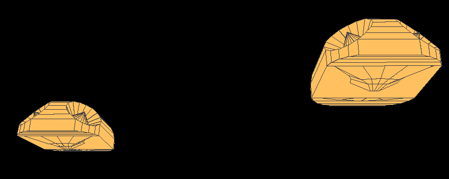
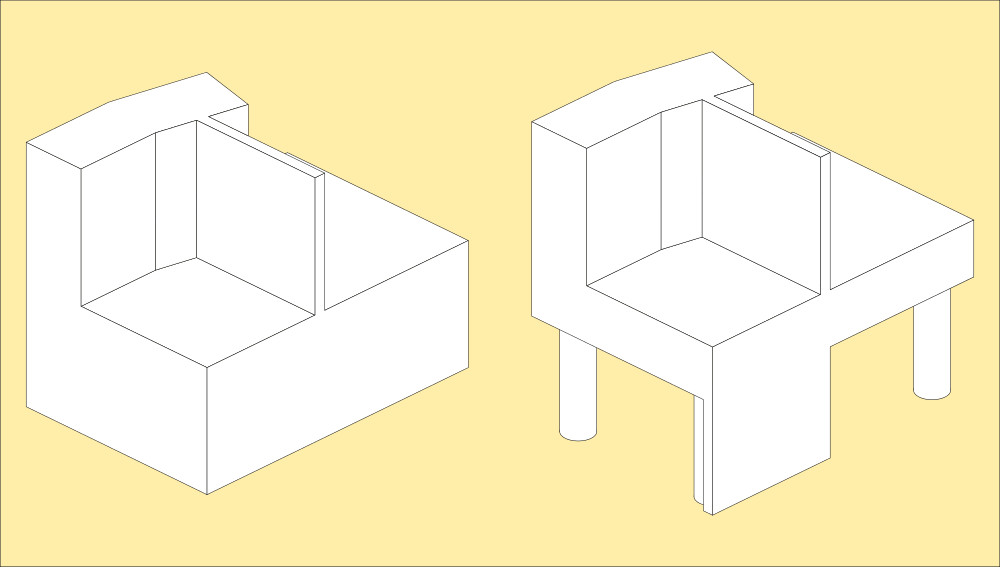
Here is an imaginary representation of a table with a laptop and mouse on it, and a cable across the back. The robot has walked on the first image and mapped the table top but doesnt understand whats under it or around it. The cable is logged as an obstruction, breaking up the surface. I've catered for surfaces by defining the world as a solid until the robot maps it. Anything walked on becomes a flat surface on a pillar, and anything walked under then becomes a floating shelf joined to the ground plane by pillars defined by where it cannot walk. Because the robot will only ever experience things it can walk on or under, and motion in between, it makes assumptions about what is in between and just projects what it can see with its camera on it so it looks like a table.
Understanding of a table then is limited to a surface that can be walked on, above another surface that can be walked on, both with obstructions. Obstructions are treated as pillars with possible walking surfaces on top, but extend to the ceiling unless they are walked on. The robot is equipped with an accelerometer and can estimate height when picked up from the floor and placed on a table.
Here is the code used to create the image at the top of the log.
Typically the mathematical model turned out to be too correct; as a full MorningStar the cardboard has to conform to the shape and make 45-degree angles, but cut in half and with extended faces to make a lid it spreads out, explaining a lot of the problems I had with making it fit the base I'd already designed. It seemed simple enough, but I wound up fiddling with the scaling for that a bit. Now I know why, its a few percent bigger than the plan measurement and the correct mathematical model...
Now with edges, which were also a computational nightmare because of the clockwise rule used by the face normalising routines. This complication is necessary, otherwise I'd need an extra parameter in the polygon mesh explaining which direction the face is pointing in. That's encoded into the polygon by listing the corners in clockwise order... All considered, its still simpler than measuring the plans though, and now actually matches the real measurements of the printed and folded one.
In the end, I still didnt have to supply much data to digitise it, and nothing compared to scanning the damn thing, which is the other way of inputting shapes into a computer. This way is elegant and surprisingly simple when you know how - its just a matter of understanding the relationship of the parts to the whole.
from math import sin,cos,atan as atn,sqrt as sqr  # make the maths comfy

import pygame,Image                     # for realtime display
from pygame.locals import *
from time import sleep

pygame.init()                           # set it up
window = pygame.display.set_mode((1024,768))
pygame.display.set_caption("1024x768")
screen = pygame.display.get_surface()

pi=atn(1.0)*4.0                         # pi to machine resolution
d2r=pi/180.0                            # convert between degrees and radians
r2d=180.0/pi                            # and back

### subroutines ###

def test():                             # calculate overall size of entire object in mm
  global coords
  xs=[]; ys=[]; zs=[]                   # temporary lists of x y and z coords
  for c in coords:
    xs.append(c[0])                     # split the lists
    ys.append(c[1])
    zs.append(c[2])
  w=int(max(xs)-min(xs))                # find their bounding box dimensions
  d=int(max(ys)-min(ys))
  h=int(max(zs)-min(zs))
  pygame.image.save(screen,'lidmesh.png') # and dump a bitmap of the current viewport
  xs=[]; ys=[]; zs=[]
  return w,d,h

###

def qspoly(plst):                       # quicksort z coords into order
  lstlen = len(plst)                    # number of polys
  if lstlen <= 1:                       # less than 2 must be in order already
    return plst                         # return it
  elif lstlen == 2:                     # if there's only 2
    if plst[0][0] < plst[1][0]:         # and their z coords are in order already
        return [plst[0],plst[1]]        # return them
    else:                               # otherwise
        return [plst[1],plst[0]]        # swap them
  else:                                 # and return them
    pivpt = plst[0]                     # take the first poly z as a pivot point
    plst1 = []                          # make 2 empty lists
    plst2 = []
    for lstval in range(1,lstlen):      # go through all the z coords
        if plst[lstval][0] < pivpt[0]:  # if the pivotpoint z is greater
            plst1.append(plst[lstval])  # put the poly in one list
        else:                           # otherwise
            plst2.append(plst[lstval])  # put it in the other
    sort1 = qspoly(plst1)               # recursively sort the biggers list
    sort2 = qspoly(plst2)               # and the smallers list
    result = sort1 + [pivpt] + sort2    # then join them all together
    return result                       # and return the list

###

def angle(sx,sy):                       # quadratic angle of coords from origin
  if sx<>0: a=float(atn(abs(float(sy))/abs(float(sx)))*r2d) # angle of hypotenuse: arctan(y/x)
  if sx>=0 and sy==0: a=0.0             # point lays on origin or to right; return 0 degrees
  if sx<0 and sy==0: a=180.0            # directly to the left; 180 degrees
  if sx==0 and sy>0: a=90.0             # directly above; 90 degrees
  if sx==0 and sy<0: a=270.0            # directly below; 270 degrees
  if sx>0 and sy>0: a=float(a)          # its in quadrant 1,1; 0.n1-89.9n degrees
  if sx<0 and sy>0: a=float(180-a)      # quadrant -1,1; 90.n1-179.9n degrees
  if sx>0 and sy<0: a=float(360-a)      # quadrant 1,-1; 270.n1-359.9n degrees
  if sx<0 and sy<0: a=float(180+a)      # quadrant -1,-1; 180.n1-269.9n degrees
  return a                              # return actual angle

###

def radius(sx,sy):                      # get radius of coords from origin
  r=float(sqr((abs(float(sx))*abs(float(sx)))+(abs(float(sy))*abs(float(sy)))))
  return r                              # its pythagorus, sum of the root of the squares

def rotate(x,y,z,rs):                   # rotate a point x,y,z around origin 0,0,0
  for ra in rs.split():                 # step through list of rotates
    if ra[0]=='z':                      # z plane
      a=angle(x,y)+float(ra[1:])        # slice the xy plane, find angle and add rotate to it
      r=radius(x,y)                     # find the radius from 0,0,z
      x=cos(a*d2r)*r                    # calculate new x,y,n
      y=sin(a*d2r)*r
    if ra[0]=='x':                      # x plane
      a=angle(z,y)+float(ra[1:])        # slice the yz plane, find angle and add rotate to it
      r=radius(z,y)                     # find the radius from x,0,0
      z=cos(a*d2r)*r                    # calculate new n,x,y
      y=sin(a*d2r)*r
    if ra[0]=='y':                      # y plane
      a=angle(x,z)+float(ra[1:])        # slice the xz plane, find angle and add rotate to it
      r=radius(x,z)                     # find the radius from 0,y,0
      x=cos(a*d2r)*r                    # calculate new x,n,z
      z=sin(a*d2r)*r
  return (x,y,z)                        # return final x,y,z coordinate

###

def isfacing(crd):                      # is polygon facing up (vertices ordered clockwise)
  for n in range(len(crd)-1):           # remove duplicate coordinates
    if len(crd)>n:
      if crd.count(crd[n])>=2: crd.remove(crd[n])
  if len(crd)>=3:                       # if there's at least 3 left
    x1=crd[0][0]; y1=crd[0][1]          # pick 3 spaced equally round the perimeter
    x2=crd[len(crd)/3][0]; y2=crd[len(crd)/3][1]
    x3=crd[(len(crd)/3)*2][0]; y3=crd[(len(crd)/3)*2][1]
    area=x1*y2+x2*y3+x3*y1-x2*y1-x3*y2-x1*y3 # find poly area, if its negative its facing down
    return (area/2>=0)                  # return that, dont need the actual area
  else: return 0                        # otherwise its not a polygon

###

def buildlid(sw,sh,r):
  coords=[]                             # list of vertices
  polys=[]                              # list of polygons
  rot=['z113.5 x50 z45','z22.5 y-50 z45','z292.5 x-50 z45','z202.5 y50 z45'] # corner rotations
  minz=0
  sws=[-((sw/2)+r),(sw/2)+r,(sw/2)+r,-((sw/2)+r)] # width of side between centres of rotation
  shs=[(sh/2)+r,(sh/2)+r,-((sh/2)+r),-((sh/2)+r)] # height of side between centres
  spr=360.0/16                          # spread the points around a full circle

  for s in range(4):                    # make 4 corners
    for a in range(16):                 # with 16 segments each around the edge
      x=cos(a*spr*d2r)*r                # make a circle round the origin
      y=sin(a*spr*d2r)*r                # on the z axis
      z=0                               # on ground plane so origin is at the top
      x,y,z=rotate(x,y,z,rot[s])        # rotate the points in 3d to match the corner angles
      coords.append([x+sws[s],y+shs[s],z]) # add coordinates to vertex list
    for a in range(16):                 # another 16 segments inside
      x=cos(a*spr*d2r)*(r/2)            # make a concentric circle half the size
      y=sin(a*spr*d2r)*(r/2)
      z=-r/2.0                          # above the first, again in the z axis
      x,y,z=rotate(x,y,z,rot[s])        # rotate the points in 3d
      coords.append([x+sws[s],y+shs[s],z]) # add coordinates to vertex list
    x=0                                 # make a single point at the centre
    y=0
    z=r/8                               # slightly above the rings
    x,y,z=rotate(x,y,z,rot[s])          # rotate it into place in 3d
    coords.append([x+sws[s],y+shs[s],z]) # add it to the coords list
    if z<minz: minz=z

    for n in range(16):                 # now polygons, these point to the actual coords
      a=n; b=n+1; c=n+17; d=n+16        # point at the vertices of ring 1 and 2
      if b>15: b=b-16                   # its a grid; wrap the edges around
      if c>31: c=c-16
      if d>31: d=d-16
      p=[a+(s*33),b+(s*33),c+(s*33),d+(s*33)] # point at correct corner vertices
      polys.append([p,n<16])            # and add the poly to the list

    for n in range(16):                 # second ring
      a=n+16; b=n+17; c=n+33; d=n+32    # points at vertices of ring 2 and centre
      if b>31: b=b-16                   # wrap the edges around
      if c>31: c=32
      if d>31: d=32
      p=[a+(s*33),b+(s*33),c+(s*33),d+(s*33)] # point at correct corner vertices
      polys.append([p,n<16])            # add poly to the list

  polys.append([[40,7,106,73],True])    # add central square

  for n in range(6):                    # add surrounding polygons between the circles
    polys.append([[7+n,40-n,39-n,8+n],True])      # they are all clockwise
    polys.append([[40+n,73-n,72-n,41+n],True])    # so work out where they are from centre
    polys.append([[73+n,106-n,105-n,74+n],True])
    polys.append([[106+n,7-n,6-n,107+n],True])

  lc=len(coords)                        # make a note of the coords to point to

  for c in range(4):                    # four corner circles
    for n in range(5):                  # five points intersect with rim
      v=n                               # but they arent arranged in a decent order so
      if n>1: v=n+11                    # bodge the order of the points in the sector
      ev=v+(c*33)                       # for each corner
      x,y,z=coords[ev]                  # find the actual coordinates
      coords.append([x,y,minz-50])      # copy the rim coordinates lower to make an edge

  rim=[[1,0,0,1],[0,15,4,0],[15,14,3,4],[14,13,2,3]] # bodge the new rim coordinates to the old ones
  for a,b,c,d in rim:                   # pick up a set of corners
    polys.append([[a,b,lc+c,lc+d],True]) # and make a polygon from them
    polys.append([[a+33,b+33,lc+c+5,lc+d+5],True]) # echo for the other corner pieces
    polys.append([[a+66,b+66,lc+c+10,lc+d+10],True])
    polys.append([[a+99,b+99,lc+c+15,lc+d+15],True])

  polys.append([[13,34,lc+6,lc+2],True]) # and fill in the gaps to make complete sides
  polys.append([[46,67,lc+11,lc+7],True])
  polys.append([[79,100,lc+16,lc+12],True]) # bodge...
  polys.append([[112,1,lc+1,lc+17],True])

  polys.append([[lc+12,lc+16,lc+15,lc+13],True])    # bridge across the front edge to close the base
  polys.append([[lc+13,lc+15,lc+19,lc+14],True])
  polys.append([[lc+14,lc+19,lc+18,lc+10],True])
  polys.append([[lc+10,lc+18,lc+17,lc+11],True])

  polys.append([[lc+11,lc+17,lc+1,lc+7],True])      # fill in the middle


  polys.append([[lc+7,lc+1,lc+0,lc+8],True])        # and bridge across the back to close that too
  polys.append([[lc+8,lc+0,lc+4,lc+9],True])
  polys.append([[lc+9,lc+4,lc+3,lc+5],True])        # bodge...
  polys.append([[lc+5,lc+3,lc+2,lc+6],True])

  lc=len(coords)                        # make a note of the coords to point to

  c=[]                                  # make containers to hold some measurements
  c.append([[78,74,0],[78,74,0],[39,85,0],[0,90,0],[-39,85,0],[-78,74,0],[-78,74,0]])    # behold my shiny
  c.append([[48,34,0],[30,41,10],[14,44,10],[0,45,10],[-14,44,10],[-30,41,10],[-48,34,0]]) # quadratic
  c.append([[42,18,0],[16,25,12],[9,25,12],[0,26,12],[-9,25,12],[-16,25,12],[-42,18,0]])  # metal
  c.append([[39,0,0],[7,0,14],[3,0,14],[0,0,14],[-3,0,14],[-7,0,14],[-39,0,0]])       # ass-plate bodge ;)

  for a in range(4):                    # iterate the containers
    for n in range(7):                  # iterate the vertices in the containers
      x,y,z=c[a][n]                     # make the top half
      coords.append([-x,y,minz-50-z])   # and write it into the coords pool
  for a in range(3,0,-1):               # make the bottom half
    for n in range(7):
      x,y,z=c[a-1][n]
      coords.append([-x,-y,minz-50-z])  # write it to the pool

  for t in range(6):                    # 7 rows of vertices, 6 columns of polys
    for n in range(6):                  # 7 columns of vertices
      polys.append([[lc+n+(t*7),lc+n+(t*7)+1,lc+n+(t*7)+8,lc+n+(t*7)+7],True]) # write the polys

  return polys,coords                   # and return the complete orthogonal set

###

def renderise(msh,verts,ctr,agl):       # build a list of 2d polygons from 3d data
  global origins,scl                    # pick up the positions of the objects
  render=[]                             # make a blank scene
  for i in range(len(mesh)):            # go through all the objects
    for m in msh[i]:                    # go through all the polys in the object
      az=0                              # centroid position
      crd=[]                            # blank list of 2d coordinates for pygame.draw.poly()
      for c in range(4):                # 4 corners for hybrid 'bitmesh' polygons
        x,y,z=verts[m[0][c]]            # get the coordinates of the corners
        x=x+origins[i][0]
        y=y+origins[i][1]
        z=z+origins[i][2]
        x,y,z=rotate(x,y,z,agl)         # rotate them into 3d space
        persp=(z+1000)/1000.0           # calculate perspective distortion
        x=x*persp*scl; y=y*persp*scl    # and apply it to each vertex
        crd.append([x+ctr[0],y+ctr[1]])
        az=az+z
      az=az/4.0                         # find the average z of the four (the centroid)
      if isfacing(crd):                 # if its facing towards camera (up or +z)
        render.append([az,crd])         # render it
  return render

def savemesh(fil,i):                    # save the submesh as a modified wavefront format file
  global mesh,coords,origins,axes       # pick up the entire set
  f=open(fil,'w')                       # make a file
  f.write('#cardware object\n\n')       # make a header
  f.write('#parameters\n')              # write out metadata
  for n in range(len(axes[i])):         # angles of the legs are held in a chain from foot to foot
    f.write('a '+str(axes[i][n][0])+','+str(axes[i][n][2][0])+','+str(axes[i][n][2][1])+','+str(axes[i][n][2][2])+'\n')
  f.write('\no '+str(origins[i][0])+','+str(origins[i][1])+','+str(origins[i][2])+'\n')
  f.write('\n#vertices\n')              # write out vertex data
  minp=mesh[i][0][0][0]
  maxp=mesh[i][0][0][0]                 # first polygon corner vertex in submesh
  for p in mesh[i]:                     # find the all others
    for m in p[0]:
      if m<minp: minp=m                 # determine the range within the coords block
      if m>maxp: maxp=m
  print minp,maxp
  for c in range((maxp-minp)+1):        # select just submesh vertices from the master vertex list
    x,y,z=coords[c+minp]
    f.write('v '+str(x)+', '+str(y)+', '+str(z)+'\n') # and write them to the file
  f.write('\n#faces\n')
  for p in mesh[i]:                     # now go through polygons pointing to those vertices
    a,b,c,d=p[0]                        # pick up the corner vertices
    if p[1]:                            # write out the modified vertex pointers
      f.write('f '+str(a-minp)+', '+str(b-minp)+', '+str(c-minp)+', '+str(d-minp)) # if its drawn write the polygon
    else:                                                                          # otherwise
      f.write('#f '+str(a-minp)+', '+str(b-minp)+', '+str(c-minp)+', '+str(d-minp)) # just annotate it in the file
    f.write('\n')
  f.close()

def loadmesh(fil,i):                    # load a mesh into the coord and polygon blocks
  global mesh,coords,axes,origins,cx,cy # pick up mesh structures
  imesh=[]; icoords=[]; iaxes=[]; iorigs=[] # make new blank ones
  lc=len(coords)                        # make a note of the current vertex list length
  f=open(fil,'r')                       # open the file
  lst=list(f)                           # load it into a list
  f.close()                             # close the file
  icx=cx; icy=cx; icz=0                 # new instance defaults to screen center
  minx=0; miny=0; minz=0
  maxx=0; maxy=0; maxz=0
  if '#cardware object\n' in lst:       # make sure its a cardware mesh
    err=False                           # check syntax
    centre=False                        # use quadratic cartesian coordinates
    for l in lst:                       # go through lines one by one
      if l.strip()!='':                 # if its not a blank line
        if '#' in l: l=l.strip().split('#')[0].strip() # remove annotations
        if l>'':                        # if its still not blank
          if l[0]=='v':                 # if its a vertex line
            l=l[1:].strip().split(',')  # remove the preamble and snap it at commas
            x=float(l[0])               # and read it as three floating point values
            y=float(l[1])
            z=float(l[2])
            if x<minx: minx=x
            if y<miny: miny=y
            if z<minz: minz=z
            if x>maxx: maxx=x
            if y>maxy: maxy=y
            if z>maxz: maxz=z
            icoords.append([x,y,z])     # store it temporarily
          elif l[0]=='f':               # otherwise, if its a face line
            l=l[1:].strip().split(',')  # snap it at commas
            a=int(l[0])+lc              # read the pointer and modify it to point past
            b=int(l[1])+lc              # the existing coords
            c=int(l[2])+lc
            d=int(l[3])+lc
            imesh.append([[a,b,c,d],True]) # store it temporarily
          elif l[0]=='o':               # otherwise if its an origin; initial position in map
            l=l[1:].strip().split(',')  # snap it up
            icx=float(l[0])             # and make a note of it
            icy=float(l[1])
            icz=float(l[2])
          elif l[0]=='a':               # otherwise if its an articulation
            l=l[1:].strip().split(',')  # snap it up
            a=int(l[0])                 # get the id of the part and articulation it attaches to
            x=float(l[1])               # and the relative coords of the centre of rotation
            y=float(l[2])
            z=float(l[3])
            iaxes.append([a,[0,0,0],[x,y,z]]) # temporarily store the id, angles and position
          elif l[0]=='c':               # otherwise is a flag to say data is topleft or quadratic
            centre=True
          else:                         # otherwise its not supposed to be there
            print'** warning ** malformed file **'
            err=True                    # so give up on load without modifying memory

  else:
    print '** not a cardware file **' # otherwise, cant even see a proper format
    err=True

  if not err:                           # providing all went to plan
    while len(mesh)<=i:
      mesh.append([])
      axes.append([])
      origins.append([])
    for c in icoords:
      x,y,z=c
      if centre:
        x=x-((maxx-minx)/2.0)
        y=y-((maxy-miny)/2.0)
        z=z+((maxz-minz)/2.0)
      coords.append([x,y,z])  # append the new coords to the end of the coord block
    for p in imesh: mesh[i].append(p)   # add the new polygon pointers to the mesh block
    for a in iaxes: axes[i].append(a)   # attach the new part to the parts chain
    origins[i]=[icx,icy,icz]            # and give it an initial reference position

### main routine ###

cx=512; cy=384                          # centre coords of screen
r=43; sw=25; sh=80                      # morningstar template radius, side lengths
render=[]

coords=[]
mesh=[]
axes=[]
origins=[]

#msh,coords=buildlid(sw,sh,r)           # build the lid
#mesh.append(msh)
#savemesh('body.msh',0)

loadmesh('body.msh',0)
loadmesh('thigh.msh',1)
loadmesh('thigh.msh',2)
loadmesh('hipmodule.msh',3)
loadmesh('hipmodule.msh',4)
loadmesh('hipunit.msh',5)
loadmesh('hipunit.msh',6)
loadmesh('hipunit.msh',7)
loadmesh('hipunit.msh',8)
loadmesh('foot.msh',9)
loadmesh('foot.msh',10)

origins[0]=[-300,0,30]
origins[1]=[-100,0,0]
origins[2]=[-50,0,0]
origins[3]=[-100,100,-17]
origins[4]=[-50,100,-17]
origins[5]=[25,0,0]
origins[6]=[100,0,0]
origins[7]=[25,100,0]
origins[8]=[100,100,0]
origins[9]=[-100,-150,0]
origins[10]=[50,-150,0]

chg=False                               # display changed flag
xa=-90                                    # rotation of entire scene round origin
ya=0
scl=2.0

rend=qspoly(renderise(mesh,coords,(cx,cy),'z'+str(ya)+' x&ap
Discussions
Become a Hackaday.io Member
Create an account to leave a comment. Already have an account? Log In.