 Morning.Star
From Google Translate : Organised Pixels.
Hang on a minute, how'd that get into Latin anyway? :-D
Ever Closer...
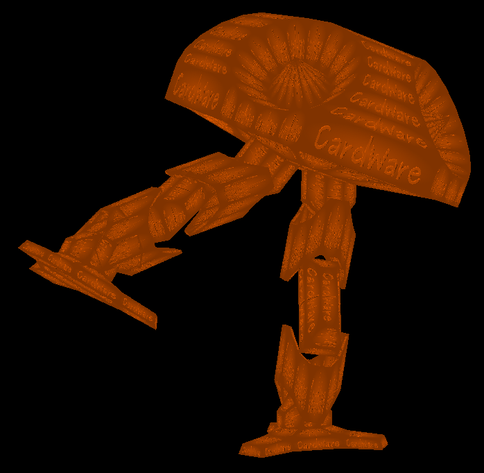
The equation governing the shape of the virtual robot now includes every single pixel on it's surface. They are all now vectors in their own right, and after a bit of tinkering with a skins editor, will all be uniquely addressable via a flat image that folds around the mesh. That's drawn using the same bitmap for every panel.
I'm only tinkering at the moment, I'm waiting for one of these to arrive.

Adafruit 12-bit 16 Channel PWM/Servo Shield with I2C interface
Yeah I know, the shame lol. I hate to resort to a shield and one from Adafruit at that, but I'm thoroughly sick of the industry making it impossible to join the various modules it uses together without their glue and platform. Plus the power supply issues were insoluble without them. The amount of servos, plus the fact they sink a quarter-amp each and need 6v meant I can no longer buy the components reliably. The rechargeable batteries run at 3.7V, which is a maddening figure. With two in series you get a little over 7V under load, which will toast a servo but not allow enough overhead for a decent 6V regulator. There are low-drop types, but they dont supply 3 amps, even the SMD ones if you can find them.
I mean, its only a chip, but unless I pay somebody to mount it with a decent power converter and all the headers I cant use it. And the Point Field Kinematics doesnt squeeze into an Atmel 328 alongside the servo sequencer.
I decided to drive the servos straight off the Pi, discovered it only had only one PWM... So I went looking and that was the first thing I encountered. Oh, nuts, I clicked BUY before I thought about it too hard.
Providing the servos run off 3.7V, and I've seen it done, this should work with my existing hardware.
Reading the limb sensors
I completely forgot about the potentiometers in the joints... A Pi has no ADC built in unlike the 328, and I need 4 for each limb, 8 in total. Even with a 328 onboard, thats still not enough, and 2 of them seems daft just for their analogue inputs.
I've done a bit of digging to see if there is an ADC I can attach to a GPIO, and Adafruit have one ready made. I can get hold of the chips for that myself, and they use SPI to communicate so that's easy.
MCP3008 - 8-bit 10-channel ADC.
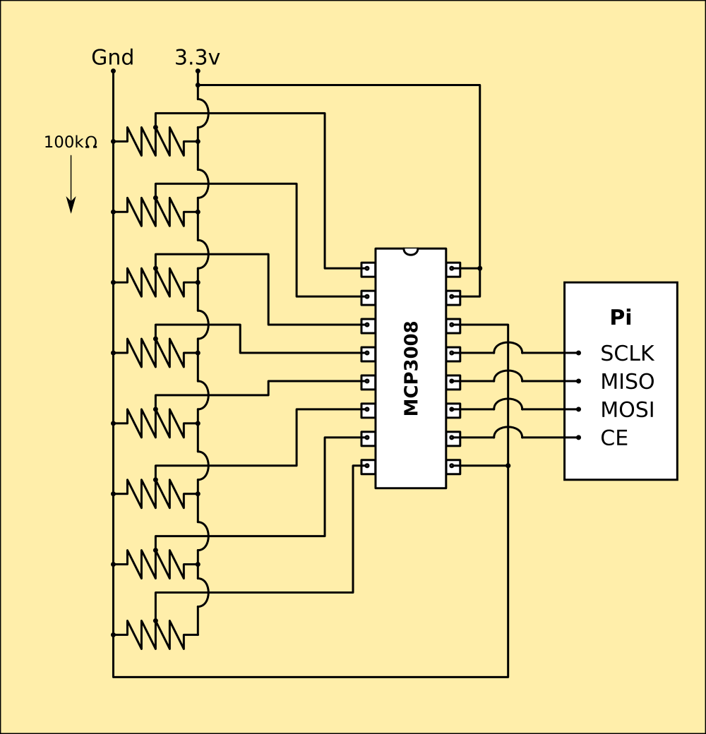 Pretty much plug the chip into the Pi's GPIOs and cable it to the sensors and thats done. Pi has software SPI so I can configure the GPIOs in code. I've ordered one, but it wont arrive until the weekend.
Bummer, I'll just have to polish some pixels until it all arrives.
Discussions
Become a Hackaday.io Member
Create an account to leave a comment. Already have an account? Log In.