 Jorj Bauer
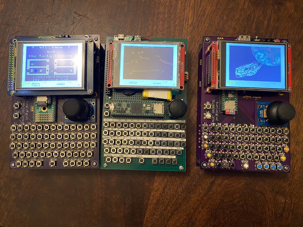
The OSH Park boards arrived, and I spent some time Monday assembling! Here's a time lapse of the build, which took me shy of 3 hours (mostly because I hadn't organized any of the parts and had to hunt for several).
The build didn't actually work right away - I'd installed the power boost module upside-down (if you use the same board, don't install it with the components facing up - they should face down). After re-soldering it, everything just booted up fine!
A couple quick thoughts about this new build.
- The speaker/headphone jack works, but it drives the headphones very heavily. Full volume is *really* loud, and since I haven't implemented the volume control yet, it's not very useful.
- The backup battery holder I had isn't exactly the one from Mouser, and I'm not sure the one I listed from Mouser is actually correct. I need to check that out.
- The Mk 1 ran directly from the battery, which seemed fine - but really isn't. As the battery runs down the backlight flickers, and if you're using a lower capacity battery, it doesn't really hold up well. The Mk 2 uses a boost circuit to pop it up to 5v, and then a dedicated 3.3v linear regulator for the display. Much nicer.
- The battery voltage tester for the Mk 1 was just a simple resistive divider, and I never quite got it working the way I wanted. I've embellished a little on the Mk 2; it's using a MOSFET and 2n3904 transistor to switch on and off the check, and I'm hoping I'll get better results (when that piece of code is eventually written).
- I decided to stick with the 18650 removable battery concept, rather than embedding a charger.
- The ESP-01 still doesn't do anything, so there's no reason for anyone to add one of those immediately. With the Mk 1 I spent a little time building an ethernet driver, but the CPU bottlenecks I ran in to caused me to abandon that path. I'm hopeful that there's enough CPU overhead in the Mk 2 - between moving to the Teensy 4.1 and moving the display to DMA - that I'll be able to pull it off with the Mk 2.
- The Teensy 4.1 is supposed to draw about 100mA at 600MHz, and the display is also rated at 100mA. The ESP-01 needs 400mA in bursts when using Wi-Fi, and probably more like 80mA when quiescent. So I've added a power switch specifically to turn off the ESP-01 -- it's not likely something anyone will use constantly, so there's no reason for it to take up a third of the power of the device!
- Speaking of power draw: I'm explicitly using the Teensy 4.1 at 528 MHz, rather than the default 600MHz. By stepping down one notch, it drops the core voltage which should significantly reduce its power draw. And in the testing I've done so far, I could probably drop it down to 396MHz (down two more steps) without affecting performance at all.
- The USB port should give me a way to add an external keyboard, which makes this more usable for non-games. I was dithering about how to deal with possible video out solutions (building a FlexIO VGA or composite output driver) but I decided I'd rather have a working handheld unit sooner, rather than waiting for a potential future that might not come to fruition. My ARM-specific FlexIO knowledge is nascent, so I'll have to spend a lot of time on this, and I don't have a lot of time to spend. And then there's the pin requirement - I'm bumping up against the number of I/O pins available! Maybe a future Mk 3 will have a video output option as a replacement for the display (like the Teensy64 does - and if the underlying uVGA project builds in Teensy 4 support, then all the more likely I'll be able to hack this together).
- The ESP-01 doesn't have a way to be reprogrammed once installed, so I installed mine on a header for easy removal. There's just enough space to do so, but I'm concerned about the WiFi antenna being right up against the back of the LCD panel. I bet this will become a problem later - but time will tell!
- I still don't have an enclosure, and if someone's interested in designing one, I'd be game for a redesign of the board to accommodate. Right now I'm using one of the three PCBs from OSH Park as a backer, with standoffs holding it together. I like it but it could be better :)
So there you have it! There are a lot of software details that need attending to now, but the basic hardware is functional. If you want to build one, OSH Park has the project shared (for a hefty $126 for 3 boards) or you can use the schematic files in the project with another manufacturer (just be sure to use the aiie_r9_gerber.zip files, which are this Mk 2 board dated 20200731).
Discussions
Become a Hackaday.io Member
Create an account to leave a comment. Already have an account? Log In.
What a great project! I hope one day, you'll make a kit out of it. I love the form factor, it's -- desirable.
Regarding your item #11, enclosure: one idea that takes very little time and effort. You could make a laser-cut front, back and perhaps side panels. All it takes is a drawing in something like InkScape, and sending that to a shop that does lasercutting. I did this for the back panel of my PiDP-11 and PiDP-10 kits. Very cheap (a few dollars), very neat. Also, you can have the laser engrave things like key legends for the top cover panel and have the tact switches poking through the cover panel. If you can't find a shop to do it locally, I'd be happy to make a one-off to try.
Kind regards, Oscar.
Are you sure? yes | no
I've definitely thought down that road, and thanks for the offer. Some day I may get to it - the keycaps for the keyboard area are the piece that is most likely to be fiddly. The joystick is probably the second most.
Are you sure? yes | no