 Jorj Bauer
There are a bunch of things I'd like to do with Aiie; I've got a good backlog. Things you've heard about, like Mockingboard support and a more reliable speaker-plus-video driver. Things you haven't, because right now they're totally made of unobtanium. And all of these things rely on the same underlying resource.
CPU time.
Having grown up with machines that clocked around 1MHz, part of my brain screams "it's 180 MHz; there's plenty in there for everyone!" It's got to be possible. I just haven't managed to make it happen yet.
So, for the last couple of days, I've been looking at ways to free up some CPU time.
Step 1: identify what's using all of it. Well, that's easy: it's redrawing the LCD.
Step 2: figure out what to do about it. There's little optimization to be done; I've already basically built my own LCD driver to be fast enough to work. Which means making a more drastic change of some sort. And here's where we go down several different rabbit holes until we strike gold. Or something.
This LCD panel - the SSD1289 - happened to be the largest sitting around my workshop. Since the original project was completely built out of stuff I had lying around, it was definitely the right choice. There was another option - I also have a a 160x128 pixel ST7735 display knocking around. That's not enough pixels for an Apple HGR display, though; so the '1289 won out.
When I originally got this panel, I was looking for fast video options for the Arduino Mega 2560. After a lifetime of working with PIC microcontrollers, I had just picked up a couple of Arduinos to see what the heck the hype was all about; I wanted to know what they were capable of. I used the panel for a small microcomputer build that ran a custom BASIC interpreter I'd thrown together and then set it all aside. (The Mega doesn't have enough RAM for this to be interesting; the display was too slow and klutzy for me; and there wasn't really any purpose behind the project other than generalized research.)
Given the platform, it seemed reasonable that a 16-bit data bus on a Mega would be faster than any SPI bus I could drive on that platform. And so it seemed like it would also be the best option for this project. More Data, More Faster.
Which is true, as long as I'm willing to spend the CPU on it. Aaaand now I'm not.
Yes, all of that means I'm thinking about what I could use to replace the display. And I've got two different ideas. First, obviously, would be to replace the display with a different but similar display. I've seen some great work with DMA on the Teensy that would probably fit the bill - offloading the CPU-based driver work to DMA, freeing up a lot of processor time. I definitely want to try this out. Prerequisite: a different display panel, which I don't have. That'll wait, then (a couple panels are on order; it's not going to wait long).
The other train of thought I've got goes something like this.
The Apple ][ could do this. The //e could do this with color and many display pages. My //e did this with a special video card; emulating that is taking a lot of CPU time. But all //es did this even without that card; they jammed video out their composite video port.
That's the point where the light bulb goes on and the cameras zoom in on our hero, grinning cagily.
Can I get all of this data out a composite NTSC interface? There exist small 3.5-ish inch NTSC monitors. Some of them are even rechargeable themselves, with auxiliary power out - so you can plug a security camera in to this thing for both video and power; set it up; and then plug it back in to its full-time gig. I could use one of those to double as both the display and the battery, which also gives me a built-in charger.
That sounds kind of interesting.
Of course, to do this, I'll have to do some of my least favorite circuit engineering. I really am not a fan of analog signal work. There are all these little bits of EE knowledge that are different depending on what kind of signal strength or frequency you're talking about. And they're actually really, really important.
About 15 years ago I got my amateur extra license to stretch in to analog signals a bit. I had, at the time, been playing with broadcast RF; I was teaching myself some things about transmitter and receiver design. My number one takeaway is that I don't know enough about analog design to be able to greenfield build anything more than a toy transmitter or receiver.
But this is exactly that - a toy video modulator. I think I can pull this off. I've got a couple small NTSC video panels lying around; and if I really need it, there's a 9" black and white CRT TV out in my shed (waiting for the next electronics recycling day, actually; it's time for it to go, already).
How, then, does NTSC video work? Back in the early 90s, I picked up a reference book on the subject; titled something like the "NTSC Handbook". I can still see the cover in my head. Can I find the book in my house? No, of course not. (I probably got rid of it with the first my 9" black and white CRT TVs about a decade ago.) But the difference between 1991 and now, of course, is that in 1991 I couldn't just search the internet and get all the same data, faster. (Albeit slightly less topical and curated.)
Some quick internet searches later, then, and I find an excellent reference for NTSC timing; and many sources that tell me about the 263 lines of any NTSC frame. I'm not worried about using the second 263 interlaced lines to get "full" vertical resolution; there are easily 200 visible lines in there, and Aiie is only using 192 of them anyway.
And anyone that doesn't know about the craziness in NTSC was just lost. 263 lines, but only 200 visible?
Well, each line of an NTSC signal is 63.55 microseconds long.
The first 9 lines of any NTSC signal use that time for synchronization and calibration pulses.
Then lines 10-19 have no actual data in them. In modern terms: they have the meta-data, but no pixel data.
The remainder of the 244 lines can actually be used. Sort of. Remember that this is all analog; we're spitting out a fairly messy signal, and some piece of electronics on the other end is trying to interpret voltage and timing differences to display what we're sending. The process is inherently messy - a difference in calibration on the sender and receiver would mean a difference in the display of the data.
Notably: the way this stuff was displayed on Cathode Ray Tubes means that the top and bottom lines are probably at a curved edge of the glass. That edge is generally covered up by a piece of plastic to make it look pretty on the outside. So the first few lines and the last few lines may very well be distorted or obscured, depending on the quality of your specific TV set. (The left and right edges, too; but I'm focused on the lines right now.)
It's sensible, then, to ignore a chunk of the top and bottom as suspect. Maybe they're visible. Maybe they're not. So if you need fewer lines, you pick the ones in the middle and leave the edges blank. (Or some solid color, if you're a Commodore.)
So what signals do we need to generate? Well, for black and white, we need five different voltage levels.
All of this has to be less than 1 volt. How much less than 1 volt? Well, it's messy analog. It doesn't matter too much. Let's aim for 0.75v. That'll be full on.
We also need a full off (0%); a Blank level (28.6%); a black level (34%). With those we can do simple black and white. A simple resistor network should do the trick. I don't know of any simple way to design it, without just doing an R2R ladder network of equal values and adding up bits. But I want to use a few pins as possible, so I'm going to do this differently - an uneven resistor network and some judicious application of Kirchoff.
Let's start here, modeling the TV and a simple circuit to get some voltage in to that TV's RCA input...
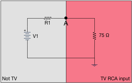
The standard impedance of a TV's RCA input is 75 ohms. Let's ignore the meaning of "impedance" for a minute, and treat that as a resistor. Then if we have a simple circuit on the outside, where some voltage runs through some resistance; and point "A" represents the physical input to the TV; this looks like a simple voltage divider. The voltage at point A is (75 * V1) / (R1 + 75). The Teensy has 3.3v outputs, so V1 is easy; given that, we can simply calculate whatever resistors we want, and use one pin for each voltage we're targeting.
Of course, I didn't do that. It would have been too simple. I wanted to reduce the number of pins I needed - not for a lack of pins, because we're talking about reclaiming something like 20 pins from the Teensy by removing the display. No; it's more because Kirchoff circuit simplification was always one of my favorite parts of EE.
If we think about just 2 general-purpose IO pins of the Teensy – where they are either at +3.3v or +0v (ground) – then it looks like this:
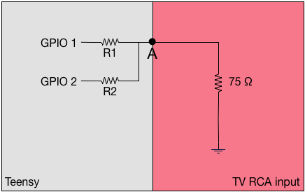
Individually, those look exactly like a standard voltage divider. But what happens when they're both enabled? Well, then it's fundamentally the same as this:
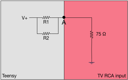
The simple formula for effective resistance of two resistors in parallel (R1 and R2) says it's R1×R2/(R1+R2). But that's the simple case if just two. The general case fir the equivalent resistance (Rv) is (1/Rev) = (1/R1) + (1/R2) + ... + (1/Rn). So we can easily calculate what the effects of any given set of resistors is in a simple ladder network: whatever bits are "on" (presenting +3.3v), we parallelize all of those pins' resistors; and then through it through the voltage divider network. Out the other end pops a value.
There's one last bit of tuning. The 75 ohm value in the TV RCA input doesn't have to be a limiting factor. We can put that in parallel with other resistors too - with side effects, but let's ignore those for now. This gives you a little more flexibility in choices for your resistors - and the model of the final circuit might look like this:
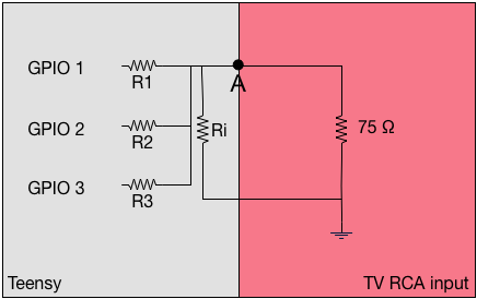
From there it's a bit of solving equations to figure out what you want the resistors to be. The difficulty, of course, is that there are a set of standard resistor values which are typically true within 10%; you can't just say "I want a 1067 Ω resistor". Instead you have to settle for a 1.1kΩ; assume that's between 990 Ω and 1210 Ω; and compensate elsewhere.
Anyway: I wrote a couple of overly complicated perl scripts to do the work for me, and came up with this set.
| R1 | 1kΩ |
| R2 | 820Ω |
| R3 | 470Ω |
| Ri | 220Ω |
Ri of 220Ω gives an effective input impedance of 56Ω (the reciporical of 1/220 + 1/75).
The maximum voltage I'll get is 0.72v. The table of pin combinations and effective voltages/percentages of "maximum" is:
| GPIO1 | 0.2v | 27.7% |
| GPIO2 | 0.24v | 33.3% |
| GPIO3 | 0.39v | 54.1% |
| GPIO1 + GPIO2 | 0.41v | 56.9% |
| GPIO1 + GPIO3 | 0.55v | 76.3% |
| GPIO2 + GPIO3 | 0.58v | 80.5% |
| GPIO1 + GPIO2 + GPIO3 | 0.72v | 100% |
Those aren't particularly evenly spaced, but it's good enough for a proof of concept. It should answer the question, "can I actually draw 2-bit grayscale NTSC?" I'll use 0v for SYNC; GPIO1 for BLANK; BPIO2 for BLACK; and GPIO 1+2+3 for WHITE. The other combinations are levels of gray.
Next up is generating the actual signals.
For lines 1-3 and 7-9, it's 2.3 µs SYNC and 29.5µs of BLANK, twice each. For lines 4-6, it's 27.1 µs of SYNC and 4.7µs of BLANK, twice each. Those let the TV figure out what your voltages and timing are.
Then comes the fun stuff. From lines 10 through 263, we have these:
- The "Front Porch" - a 1.5µs BLANK;
- The Sync - 4.7µs of SYNC;
- The "Back Porch" - a 4.7µs BLANK;
- image data, between BLACK and WHITE for 52.6µs.
The width of the "pixels" (they're not really pixels, but you can think of them that way) depends entirely on how much time you spend on each one. If you make the pulses longer, the pixels are wider. You've got 52.6µs to divide up however you like.
Let's start simple - 25 on/off transitions...
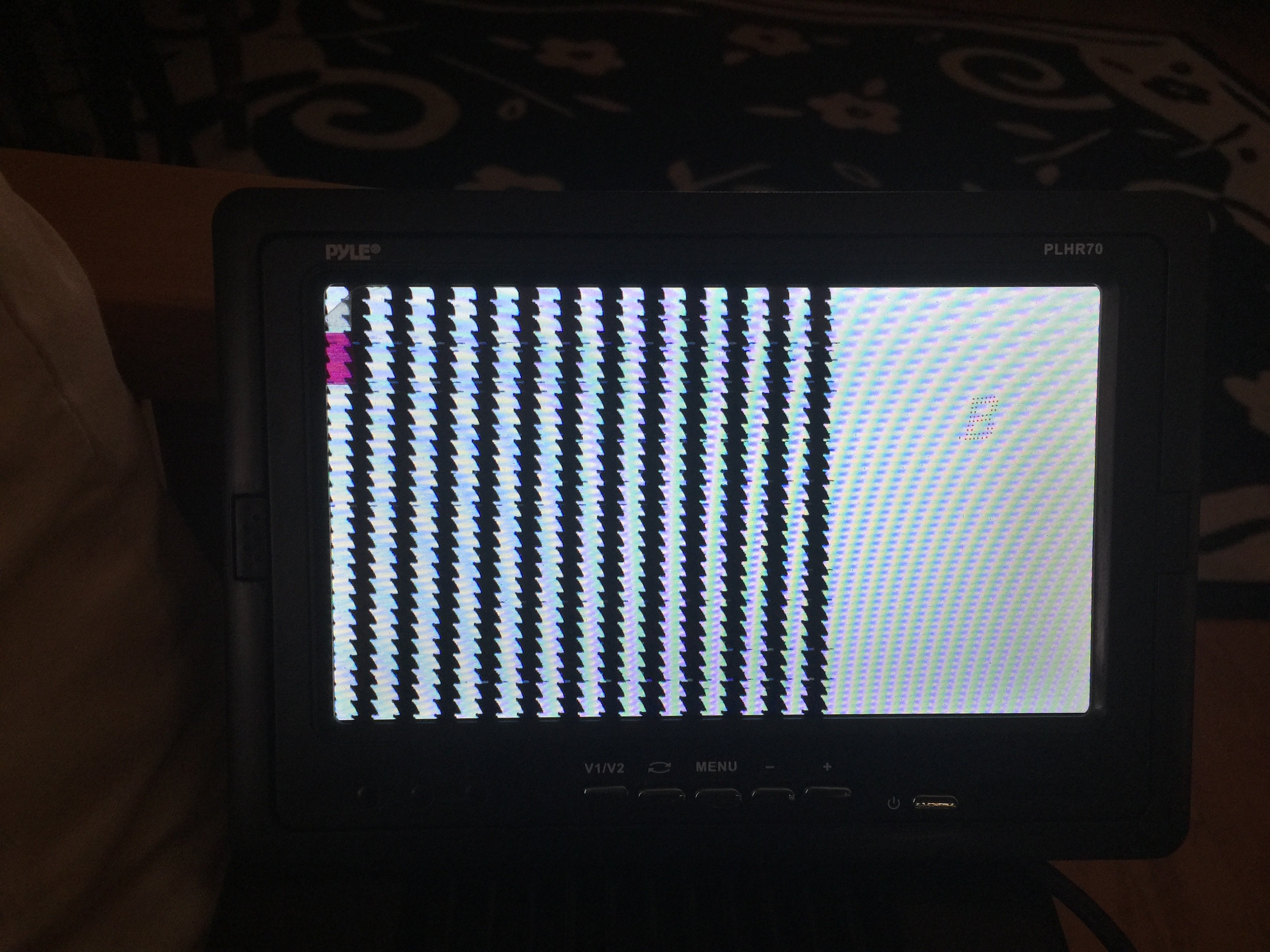
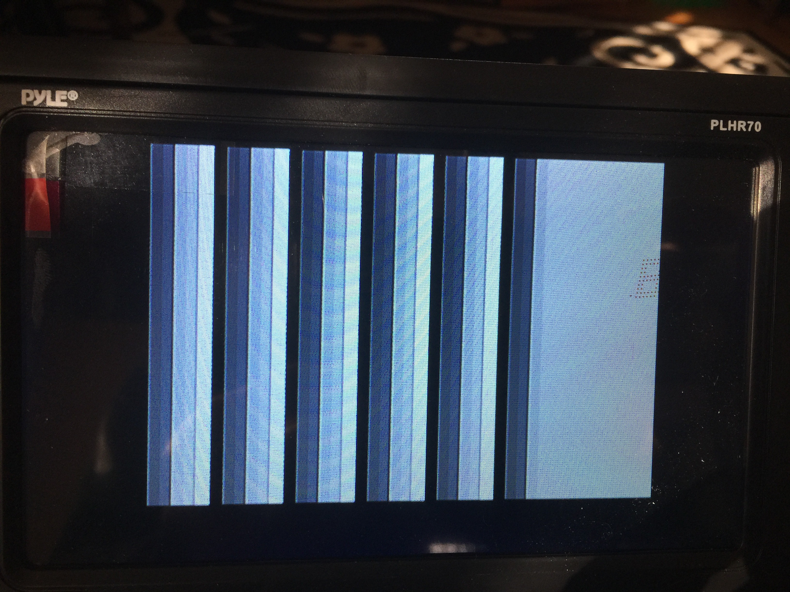
Close! The saw edges tell me that my timing isn't quite right; something is affecting the 62.55µs line timer. Find that bug and fix it, and then let's try some gray...
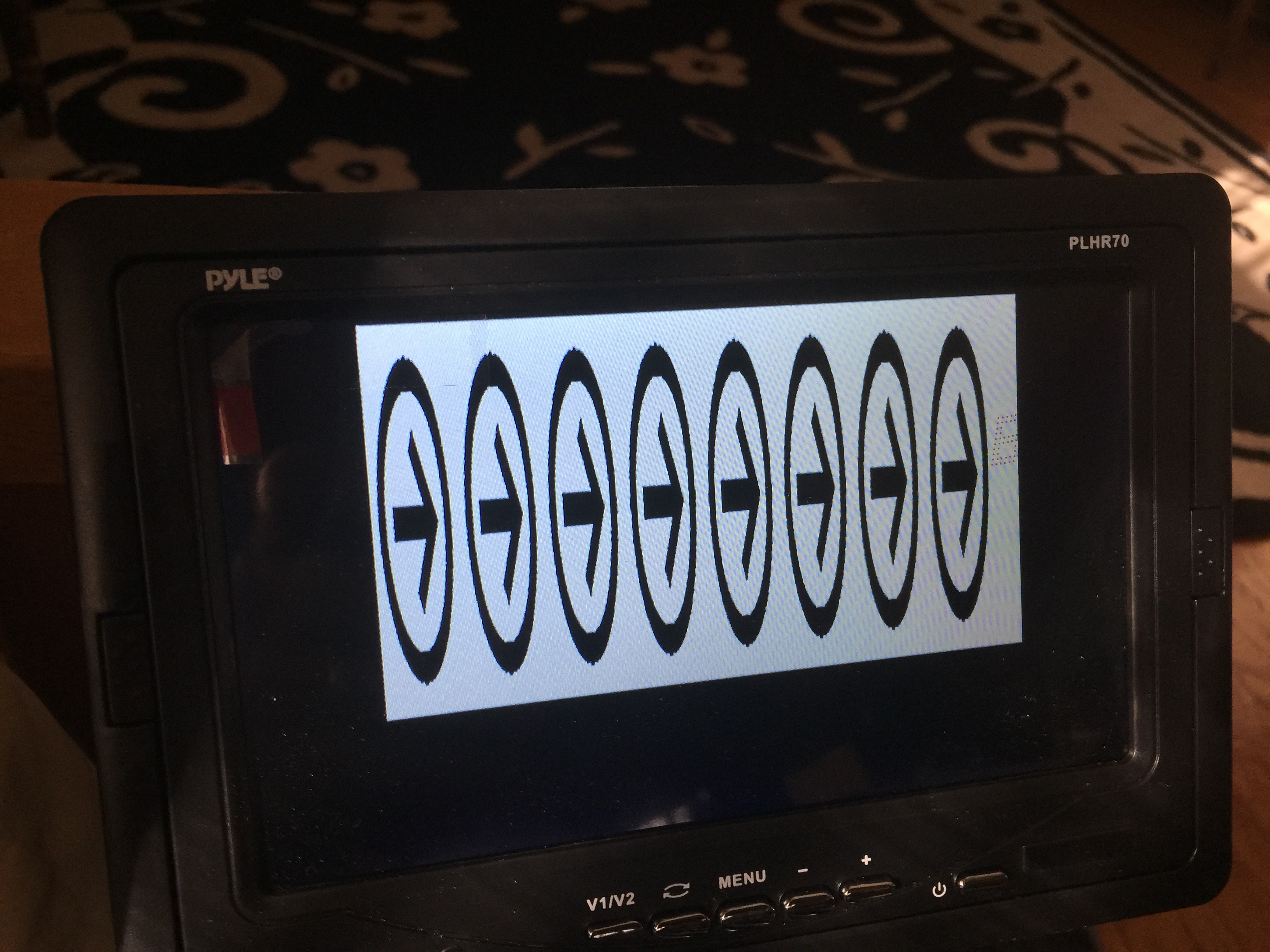
Nice. Next up, can I read from a data buffer fast enough to fill the screen with an image? Well, a quick Internet Image Search for icons, to find something simple to turn in to a C data structure; then some XPM coding, and adding a video buffer to this test project...
... and then ...
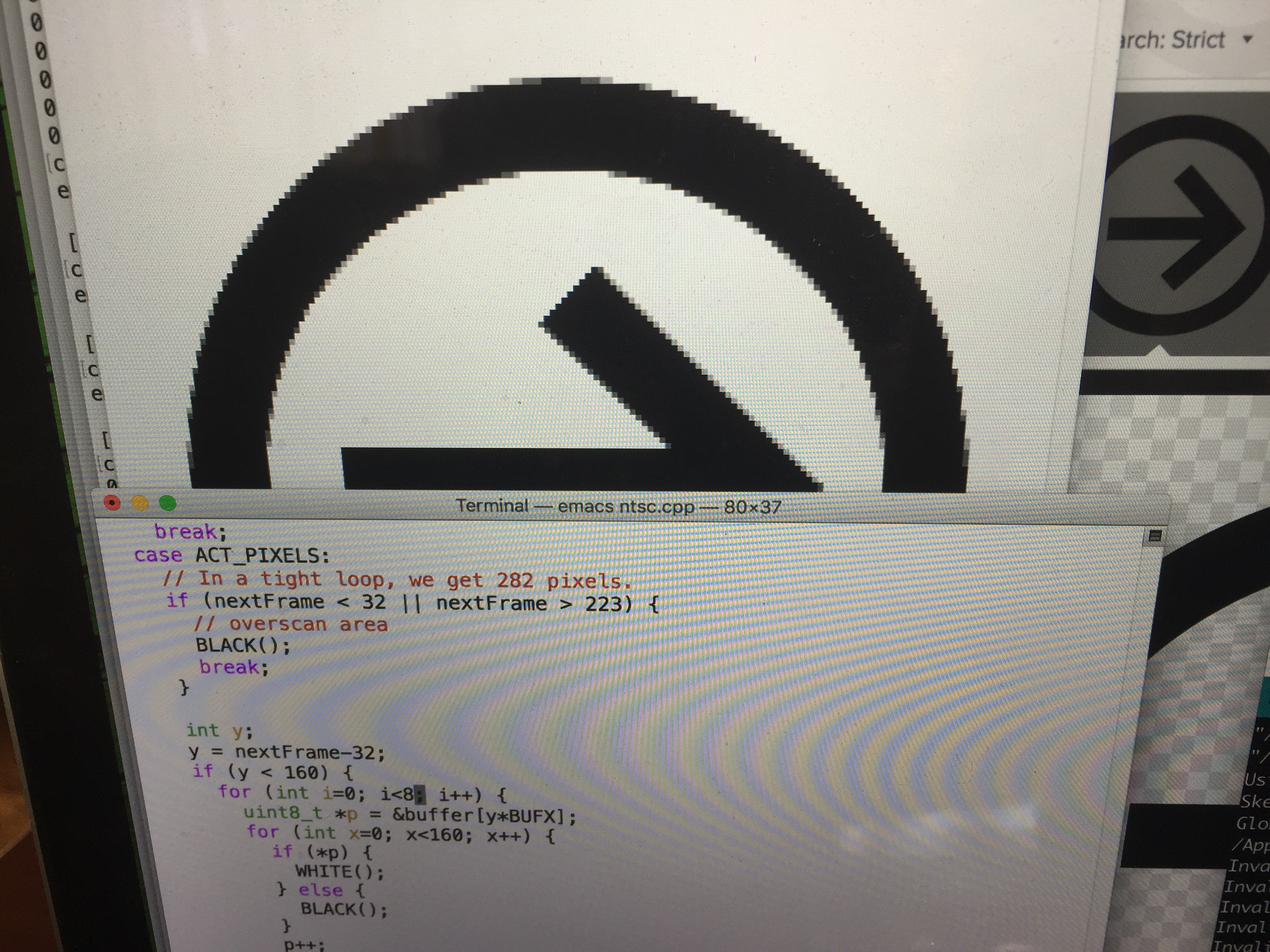
Sweet. If I turn down the delays, how many of these 160-pixel-wide images can I squeeze in to 56-ish µs?
Well, that's a pretty impressive 1280 pixels wide, plus some space at the right. (The Teensy is also 240MHz overclocked, but hey, I wanted to understand the limits.)
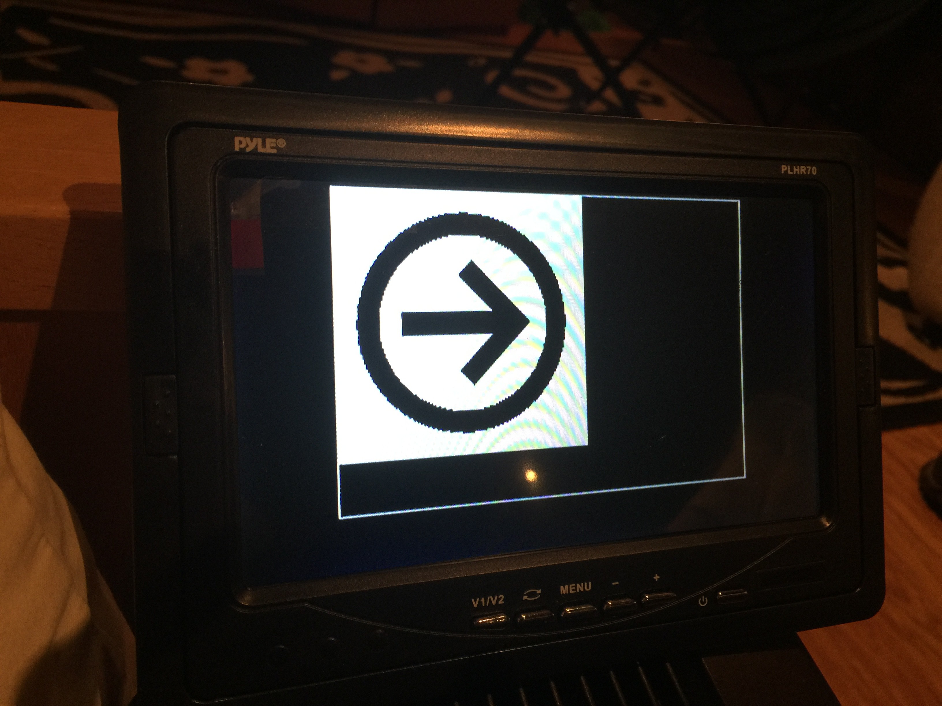
What if I marry this test project code and the Aiie! Teensy video driver? Well...
The video signal isn't quite wide enough (that is to say, the time I'm spending sending each pixel is too short), and the line sync is a little off (you can see the image wavering in spots); I'm sure those would be fixable if I wanted to go down this path any further.
Which I don't, for two reasons.
Reason 1: I'm not sure this buys me much, other than a higher framerate. The CPU overhead of driving the NTSC display is slightly lighter weight than the LCD. But I haven't started talking about color, which adds another level of complexity; and I'd still need to block for 56-ish µs to draw each line of pixels. Each clock cycle is .977 µs, so that's roughly 57 clock cycles. Right now I run the virtual CPU 48 clock cycles ahead, so the speaker has some buffered "history" to replay a teeny bit out of sync. I don't really want to make that delay longer (more RAM use and the audio will be more out of sync). I'd have to use lines 1-20 (and 213+, which I'm not using at the bottom) of the NTSC raster to run the CPU faster deliberately, and then hope the audio plays back well enough while the NTSC code is blocking the CPU from buffering more. In total it would be just shy of 11,000 clock cycles out of skew. I'm sure I could reclaim a lot of that time with nested interrupts, but that brings me to...
Reason 2: the interrupts for the NTSC timing, along with the interrupts for the CPU and Speaker, interact in ways that I'm not comfortable with at the moment. In theory, I've got four interrupts that can operate independently. They should be able to nest (where one interrupt interrupts another interrupt). I just don't understand something about how that works, because I wind up with errors like that timing issue in the video.
I'll probably spend some more time trying to understand interrupts on the ARM until the new displays arrive. Then it'll be time to play with DMA...
Discussions
Become a Hackaday.io Member
Create an account to leave a comment. Already have an account? Log In.