 Jorj Bauer
As part of the RA8875 display work, I had to build a new framebuffer and use the Teensy's eDMA system to automatically shuffle bytes out the SPI interface. In doing that I learned quite a lot about how the eDMA interface works, and what the magic code in the ILI9341 and ST7735 libraries does. I left a lot of those comments in my RA8875_t4.cpp module but I thought an out-of-band write-up would be really useful (for me for later, if not for others trying to do the same thing).
To begin with: download the IMXRT 1060 Manual from PJRC. The inner workings of all of this is documented in there, but it's not all in one place and can take a while to find (in the 1100-whatever pages of documentation). Eventually you'll be looking for data from it.
For me, the general path of getting this all working was:
- Get the display initialization working by reading other sources and duplicating what they did.
- Implement synchronous transfers on-demand to draw pixels, clear the screen, and whatnot.
- Build a framebuffer and update that instead of calling the synchronous methods.
- Build a synchronous update from the framebuffer.
- Implement a one-time DMA-to-SPI transfer that reads from the framebuffer and then stops.
- Turn on continuous asynchronous updates from the framebuffer.
- Remove all of the (now-unused) synchronous code.
The display initialization and LCD workings I'm not going to talk about too much - mostly it was a combination of looking at the RA8875 module distributed with Teensyduino 1.56 and looking up constants in the official display manual. The same is true of synchronous transfers -- a lot of copy/paste/delete/rewrite as I began to understand how the display itself works.
The framebuffer code itself is pretty straightforward. I needed an array for 8bpp 800x480, and declaring it is relatively straightforward:
DMAMEM uint8_t dmaBuffer[RA8875_HEIGHT][RA8875_WIDTH] __attribute__((aligned(32)));
A refresher from my last log entry: DMAMEM tells the Teensy to put it in RAM2, which is perfect for DMA to use; the height and width constants are 800 and 480 respectively. That just leaves the attribute, which is important for DMA -- it can apparently be picky about the alignment of the buffer it's copying out of. (I didn't have any problems with this, but then again I was forewarned and added the attribute. YMMV.)
From there it's just a matter of doing some pixel math -- whenever something needs to be drawn to the screen, calculate the proper index in to the array and store the pixel instead of pushing a command to the LCD to do the same work. Taking that buffer of data and feeding it to a synchronous update proves that I know how to interact with the display itself - initializing its display window, starting a new SPI transaction, telling it I'm sending memory data, and ending the transaction when done. Nothing difficult so far, just very very slow to perform its work. This is how I'd transfer all of the data to the display in a synchronous function:
  _writeRegister(RA8875_CURV0, 0);
  _writeRegister(RA8875_CURV0+1, 0);
  _writeRegister(RA8875_CURH0, 0);
  _writeRegister(RA8875_CURH0+1, 0);

  // Start it sending data
  writeCommand(RA8875_MRWC);
  _startSend();
  _pspi->transfer(RA8875_DATAWRITE);

  for (int idx=0; idx<800*480; idx++) {
    _pspi->transfer(dmaBuffer[idx]);
  }
  _endSend();
Those first four writes tell the display we're starting in the upper-left corner (Vertical and Horizontal cursor position at 0). Then send a memory write command; begin an SPI transaction with _startSend(); tell the display we're going to stream the pixel data; actually stream te pixel data; then end the transaction and we're done.
All we have to do is repeat that from a DMA handler!
Arr, but here there be dragons. Or maybe that's the wrong metaphor. Here there be performers of the dark arts? Certainly poorly documented capabilities that are hard to figure out from scratch. Which is why I leaned a lot on the ILI and ST code.
A lot of the code in the ILI and ST modules are abstractions -- "how do we talk to this piece of hardware to perform the some action" -- and it makes it difficult to read any of it. Paring it down to the minimum for the platform I was interested in helped a lot in seeing the important pieces. But time consuming and mind numbing. The code I'm left with is specific to the Teensy 4.1, which makes it a lot more legible.
There are a bunch of state variables. The pin assignments themselves for SPI communication are obviously in _cs, _miso, _mosi, _sck, and _rst. Pretty much everything else is more difficult to understand, so let me walk through it here.
There are the output hooks. There are multiple SPI busses on the Teensy, and in order to abstract which one is being used, there's _pspi that points to the SPI bus in question. It's also referenced in _spi_num (0, 1, or 2) and there's a crazy hack (that will certainly break at some point) to dig the SPI hardware configuration out of the SPI object and store it in _spi_hardware. Lastly we have _pimxrt_spi, which points at the low-power SPI data structure used to control how the target LPSPI bus operates.
There are the DMA glue hooks. There are a bunch of DMASetting structures, each defining a piece of data to be transferred via DMA. There's _dmatx which defines (and interacts with) the current DMA channel being used. There's _pfbtft that points at the frame buffer. _dma_state just holds a number that tells us what pieces of our DMA engine we've dealt with so far (have we initialized yet? Are we in continuous update mode? Is there a transaction active?) We have _spi_tcr_current, which refers to the current Transmit Control Register status; _spi_fcr_save which saves the Fifo Control Register setting before we start a DMA transfer so it can put it back the way it found it; and _dma_frame_count which is just a count of the number of full frames we've sent to the display (so Aiie can calculate frames per second).
The way it all works is this...
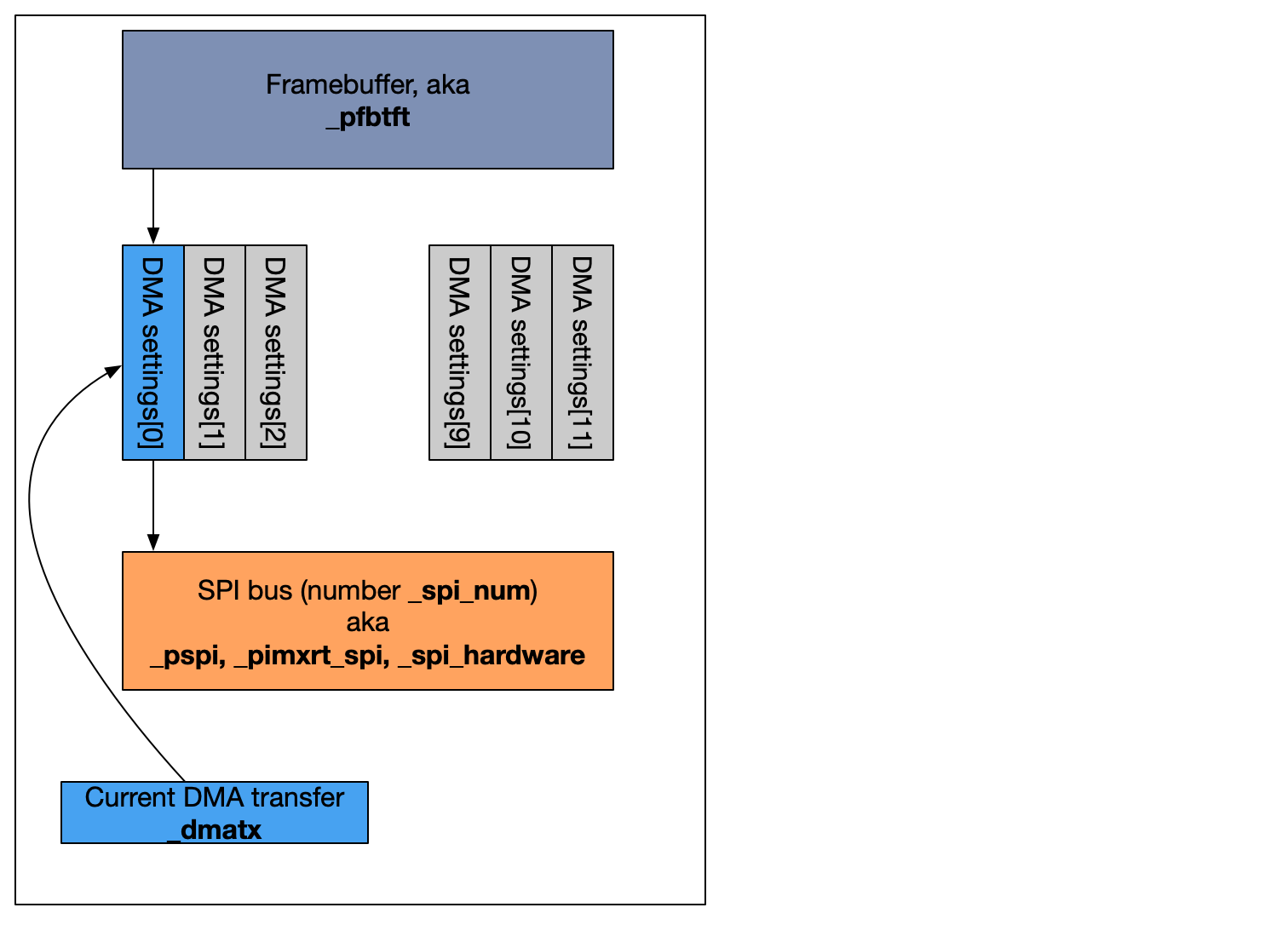
There are a number of DMASetting objects in that array sitting between the Framebuffer and the SPI bus. Each DMA transfer can only transfer up to 32767 words of data (where a word might be 8 bits, 16 bits, or 32 bits wide). We've got 800 x 480 (8-bit) words of data to write, so we will need (800*480)/32727 = 11.719 settings objects to describe all of the data. To that end we've got 12 of them, each of which will transfer (800*480)/12 = 32000 bytes of data and then hand off to the next DMASetting object.
Each object looks something like this...
| What | Notes | |
|---|---|---|
| sourceBuffer | The source pointer to the data we want to transmit | |
| destination | The peripheral target that will get the data | |
| TCD->ATTR_DST | Transmit destination attributes (word size) | |
| replaceSettingsOnCompletion() | Another dmaSetting structure that will automatically be used when this one completes |
For us, the source points to some piece of the framebuffer; the destination points to the transmit control register (TCR); the destination attributes specify that each transmit will be 8 bits; and each one refers to the next in the chain for completion, so that structure [0] points to [1]; [1] points to [2]; and so on, with the last one (number 11) pointing back to [0].
The last one in the chain is also a little special. It triggers an interrupt when it's done so we can hook the end of a transfer if we need to.
With all of that prepared, we set up _dmatx to point to the first set of the settings; tell it to trigger based on transmit status of the output SPI channel; attach the correct DMA interrupt handler; tell it to start running; and record that it has been initialized (for our own bookkeeping in _dma_state).
    _dmatx = _dmasettings[0];
    _dmatx.triggerAtHardwareEvent(dmaTXevent);
    if (_spi_num == 0) _dmatx.attachInterrupt(dmaInterrupt);
    else if (_spi_num == 1) _dmatx.attachInterrupt(dmaInterrupt1);
    else _dmatx.attachInterrupt(dmaInterrupt2);
    _dmatx.begin(true);
    _dma_state = RA8875_DMA_INIT | RA8875_DMA_EVER_INIT;
Now that the DMA channel end is set up, we'll just need to set up the display so it knows what to do with the data it's about to receive. You'll recognize this from the synchronous send I'd written above, we just stop before sending any of the actual data...
  _writeRegister(RA8875_CURV0, 0);
  _writeRegister(RA8875_CURV0+1, 0);
  _writeRegister(RA8875_CURH0, 0);
  _writeRegister(RA8875_CURH0+1, 0);

  // Start it sending data
  writeCommand(RA8875_MRWC);
  _startSend();
  _pspi->transfer(RA8875_DATAWRITE);
And then set up some registers for DMA:
  // Set transmit command register: disable RX ("mask out RX"), enable
  // TX from FIFO (b/c it's not masked out), and 8-bit data transfers
  // (7+1).
  maybeUpdateTCR(LPSPI_TCR_FRAMESZ(7) | LPSPI_TCR_RXMSK);
  // Set up the DMA Enable Register to enable transmit DMA (and not receive DMA)
  _pimxrt_spi->DER = LPSPI_DER_TDDE;
  _pimxrt_spi->SR = 0x3f00; // clear error flags
  _dmatx.triggerAtHardwareEvent( _spi_hardware->tx_dma_channel );
  _dmatx = _dmasettings[0];

  _dma_frame_count = 0;
  _dmaActiveDisplay[_spi_num]  = this;

  _dmatx.begin(false);
And finally start everything flowing.
_dmatx.enable();
Now we've started an SPI transaction; sent the commands to tell the RA8875 to write to RAM; and wired up memory to send the dmabuffer contents out SPI. When it's done it will call the interrupt, and then we need to clean up and end the transaction, or the SPI bus will hang waiting for something to end the current transaction.
That cleanup happens in process_dma_interrupt. If we're running continuously, we don't have to do much. The window rolls over from the bottom-right pixel to the top-left and the stream of data continues to flow to the screen. We additionally call a cache-busting function to tell the processor to flush and cached data to RAM before we try to use it.
But if we called updateScreenAsync(false), then it wants to update once and stop. This is the clean-up code that makes sure we're done sending, cleans up some registers and turns off the transmission circuitry, finally ending the SPI transaction and updating _dma_state so we know it's no longer running:
    while (_pimxrt_spi->FSR & 0x1f) ; // wait until transfer is done
    while (_pimxrt_spi->SR & LPSPI_SR_MBF) ; // ... and the module is not busy
    _dmatx.clearComplete();
    _pimxrt_spi->FCR = _spi_fcr_save;
    _pimxrt_spi->DER = 0; // turn off tx and rx DMA
    _pimxrt_spi->CR = LPSPI_CR_MEN | LPSPI_CR_RRF | LPSPI_CR_RTF; //RRF: reset receive FIFO; RTF: reset transmit FIFO; MEN: enable module
    _pimxrt_spi->SR = 0x3f00; // clear error flags
    // DMF: data match flag set
    // REF: receive error flag set
    // TEF: transmit error flag set
    // TCF: transfer complete flag set
    // FCF: frame complete flag set
    // WCF: word complete flag set
    maybeUpdateTCR(LPSPI_TCR_FRAMESZ(7));
    _endSend();
    _dma_state &= ~RA8875_DMA_ACTIVE;
    _dmaActiveDisplay[_spi_num] = 0;
And that's it. It's not a lot of code - the RA8875_t4.cpp file is 538 lines, of which about 100 are comments. It's just poorly documented and difficult to understand.
Having done all of that - could I do it for other Teensys? Yes, the Teensy 4.0 could do this with some code changes. None of the previous Teensys have enough RAM for the frame buffer, though; the 3.6 had 256k of RAM and it's the beefiest of the predecessors.
I'll also say it's probably not worth building DMA transfers in to the RA8875 library for a few different reasons. The fact that the performance is so poor with the system clock at 60MHz (the documented maximum) limits the utility to begin with. Then you have to also decide if you want to use it at 10% of that speed by using PSRAM, or at 8 bits per pixel in RAM1 or RAM2.
The transfers themselves may be an elegant solution to avoid wasting a lot of CPU time doing busywork, but the sacrifices and general set-up are definitely ... not.

Discussions
Become a Hackaday.io Member
Create an account to leave a comment. Already have an account? Log In.