 Jorj Bauer
Now, the SainSmart LCD I'm using wasn't the only one in my house. I have some other LCDs that are SPI-driven, and are about the same size. And I deliberately didn't choose them, because I wanted some bandwidth here. And this is the first obstacle in the "make it fast" department - in addition to emulating the CPU, I'm going to need to jam data out to a display.
The Apple II memory model is reasonably simple: there is a region of memory that's used for text and lo-res graphics, and another region used for hi-res graphics. It's easy enough to write an emulator that, whenever the text/lo-res page is written to, will update the screen - and this is indeed what I did in the first pass of this emulator. But this is only good as a toy: if the VM has to redraw part of the screen every time that the CPU is trying to perform a write to that part of memory, then either the display draw has to be so fast that you complete the combination of (CPU instruction emulation + memory write + LCD update) in less time than the original processor actually used for its single instruction; or you wind up running at less than the correct speed.
So: can I take the simple path and write to the LCD faster than the original CPU? That begs a couple of questions of its own.
How fast is one instruction on the Apple //e? Well: the 65c02 in it runs at 1023 MHz; one clock cycle is essentially 1 microsecond. Instructions on the 65c02 take different numbers of clock cycles, but average around 3 clock cycles. So a write to RAM might take 3 microseconds.
How fast can we write to the LCD? That's more complicated; with the LCDs in my house, I'm looking at either SPI or parallel busses. With an SPI bus you need just a few pins, but you have to clock out every bit: sending all 8 bits of one byte to the display, therefore, takes 8 times as long as if you happen to have a parallel bus that lets you send all 8 bits at once. All other things being equal, then: assume the chips on the displays have the same protocol, and you need to send the same data to set a 24-bit color to an arbitrary pixel on the screen - it's clear that if you need the speed, you want the parallel bus. And the SainSmart I've got has a 16-bit parallel bus, which is all the better.
Now: sending one pixel to this 16-bit parallel bus means doing something like this:
- assert the command line
- put the command byte for "set position" on the bus
- pulse the write line
- clear the command line
- put the horizontal position on the bus
- pulse the write line
- put the vertical high 16 bits on the bus
- pulse the write line
- put the vertical low 16 bits on the bus
- pulse the write line
- put the horizontal ram address on the bus
- pulse the write line
- put the vertical ram address on the bus
- pulse the write line
- assert the command line
- put the command byte "sending data" on the bus
- pulse the write line
- clear the command line
- put the pixel color data on the bus
- pulse the write line
... where I've even simplified the "color data" part. A whopping 20 steps. Let's assume, best case, that each of these takes only one clock cycle on the ARM processor. We also have a function call and return; which also means overhead for saving and restoring register state when that function is called. Let's assume that this is also best case: one instruction for the call, one for the return, one for the save, one for the restore. So we're in the neighborhood of 24/180000000 seconds - which is about 13% of our allotted time for one 65c02 instruction.
All right, it's *possible* that we could draw one pixel. But could we draw one *character*? Assuming that the character is 7 pixels by 5 pixels, we'd have to draw 35 pixels - which puts us at about 4.5 microseconds of work to perform in 1 microsecond of time. In other words: no. Our overly optimistic model says no, and the real-world version is only going to be worse.
Now, there are optimizations that can be made in all of that. Don't reposition the write cursor every time you want to draw a pixel. Use a lower-depth color format so you need to transfer less data. But still - we would need to make a pretty dramatic improvement in order to jam all this data out in real-time.
Which means the complicated way wins. In real-cpu-time, we'll need to update an in-memory framebuffer; and in the gaps between real-cpu-time, we'll update the display as fast as we can. We're going to need all of the speed we can get.
Back to the LCD, then. The SainSmart 3.2" TFT LCD I've got has this adapter board for the Mega 2560 it's supposed to piggyback on:

We will need a boatload of pins on the Teensy, though. 16 for the data bus. Reset, Read/write control lines, select line. At least. Fortunately the Teensy has 40 easily accessible I/O pins, so while this is complicated, it's not really a problem. A little bit of prototyping...
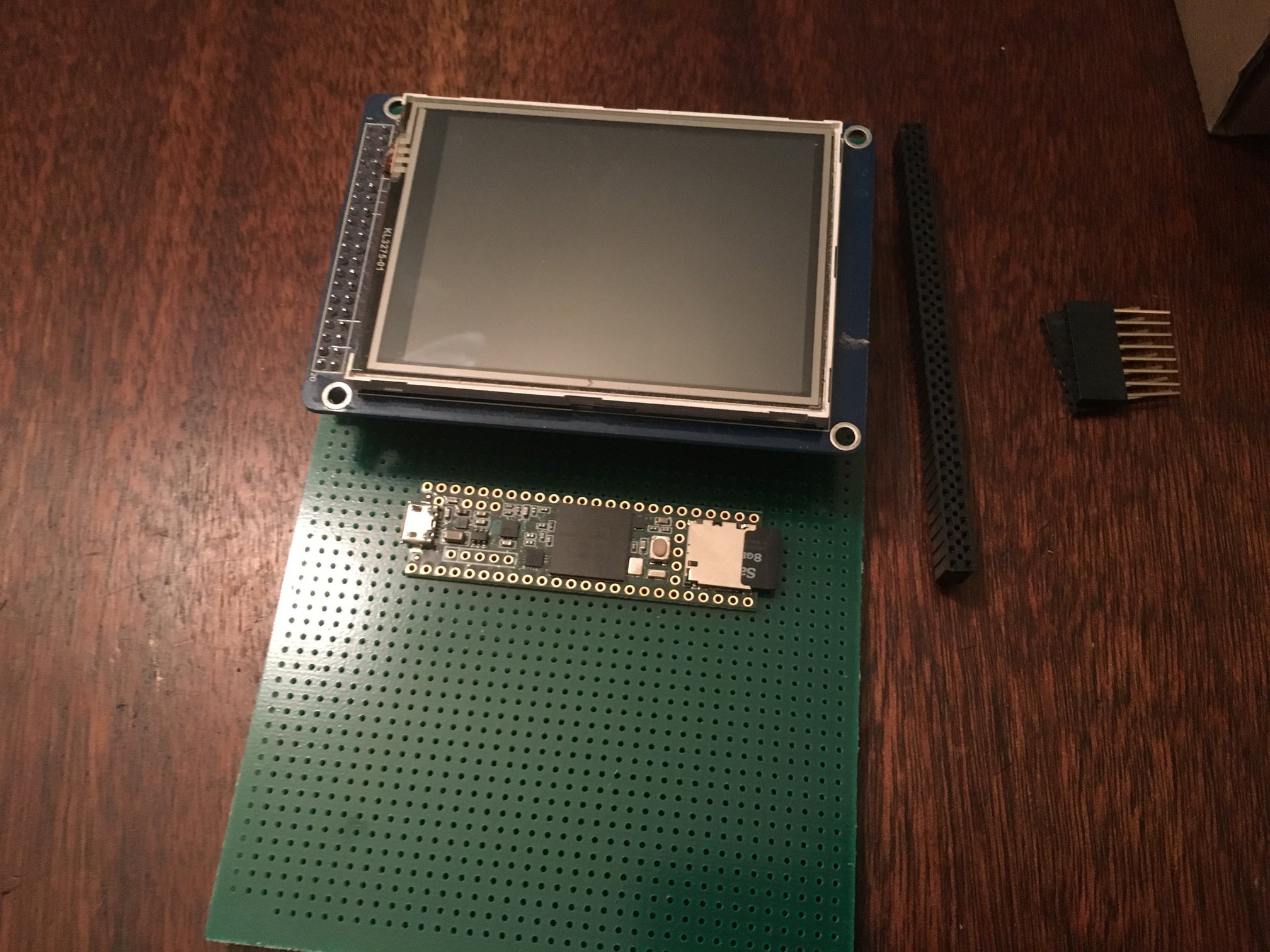
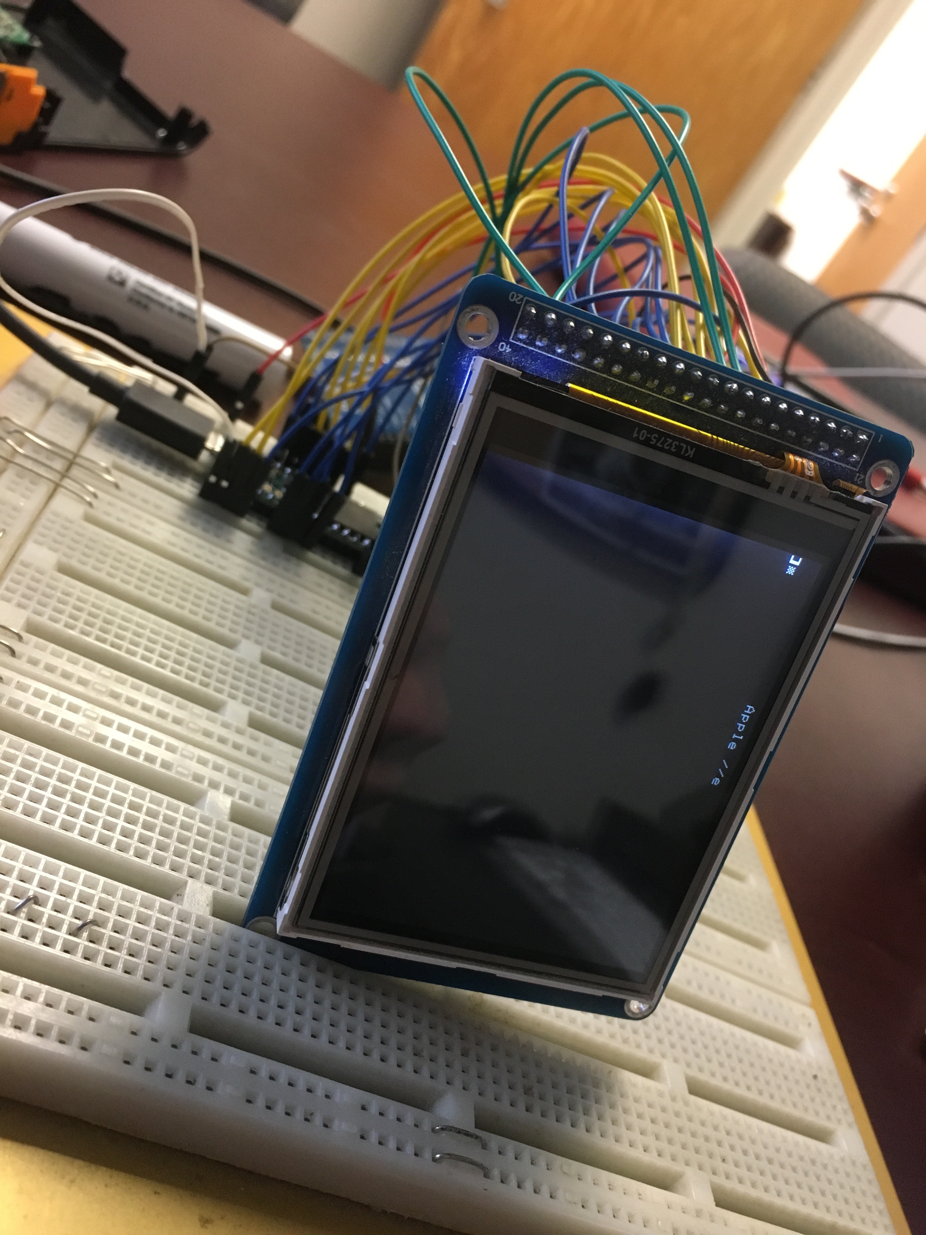
... some test wiring...

And there we go.
Discussions
Become a Hackaday.io Member
Create an account to leave a comment. Already have an account? Log In.