-
Entry 19: Pick a Peck of Pickled Prototypes
02/20/2018 at 01:10 • 4 commentsJOSS is going to take a while. Yes, it's seen the light of day, proving to me that it's possible. But there are so many pieces that I still need to code - and I'm not sure how feasible it's going to be to get the Wifi driver and USB stack written. I'm (sensibly, perhaps) keeping this in my log of to-do items as future work, and moving forward with development under Linux until I've at least got the hardware settled.
And to settle that, I need to actually make a decision about the hardware. Which is turning out to be difficult.
First: I've got a pile of different LCDs now lying around. Two different serial 320x240s. One 3.2" 480x320. One HDMI 3.5", and one HDMI 5". Each has its pros and cons.
I've also got designs on three different form factors. Two of them I can envision in cases. The other one is still basically the same device I've already built - but faster.
And continuing with the Pi Zero, I still need to build the end of the peripherals; one serial port for the printer, and two analog inputs for the joystick. Oh, and probably a third analog input for the battery level sensor?
I spent a good deal of this past weekend with papercraft and woodworking to mock up what various things would look like. It was a good use of time, even if there's nothing permanent that came out of it; my thoughts are more solid about what I want, at least.
The three prototypes I have right now are:
1. The "classic" Aiie prototype. Exactly the same form factor as the original. Small 1cm buttons as "keys" for the "keyboard" (button pad). 3.5" LCD -- probably a very nice HDMI jobbie I found on Amazon, this very nice $30 3.5" downconverting display. The LCD it's attached to is only 320x480, but it scales the HDMI input down very nicely. Power draw is pretty reasonable, too. Or, if I spend time on it, this could still be one of the 3.2" serial LCDs with a Teensy 3.6 (and external RAM).
Or, prototypes 2 and 3... a scaled-down Apple //e style -- based around either the 3.5" display or a 5" display. I really like this idea, but I want it to be functional. No fake keyboard, for example. If it's got a keyboard, then I want it to work.
And that kind of drives the direction a bit. The smallest working keyboard I can build right now would mandate a 6.5" wide model, so the 5" display *might* do. Or it might be a bit small.
In the other direction, using the 3.5" display I'd have to have keys that are about 0.2" wide. With SMD switches, I suppose it's possible; it doesn't seem like fun, and I have no idea how I would make key caps at that scale. It would be the cutest option, of course. So i'm still thinking it over (and if any of you have thoughts on a keyboard at this scale, drop me a line!).
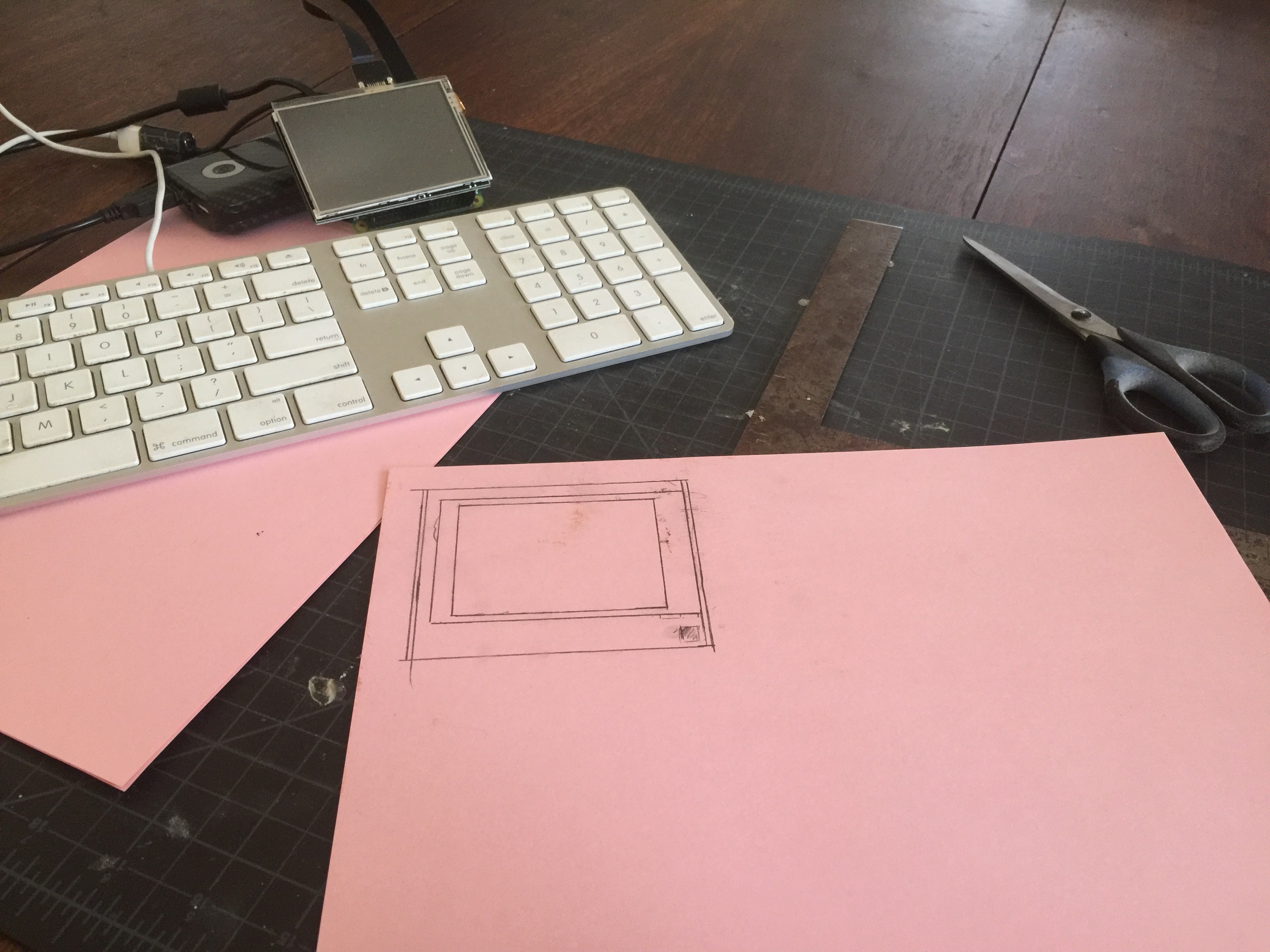
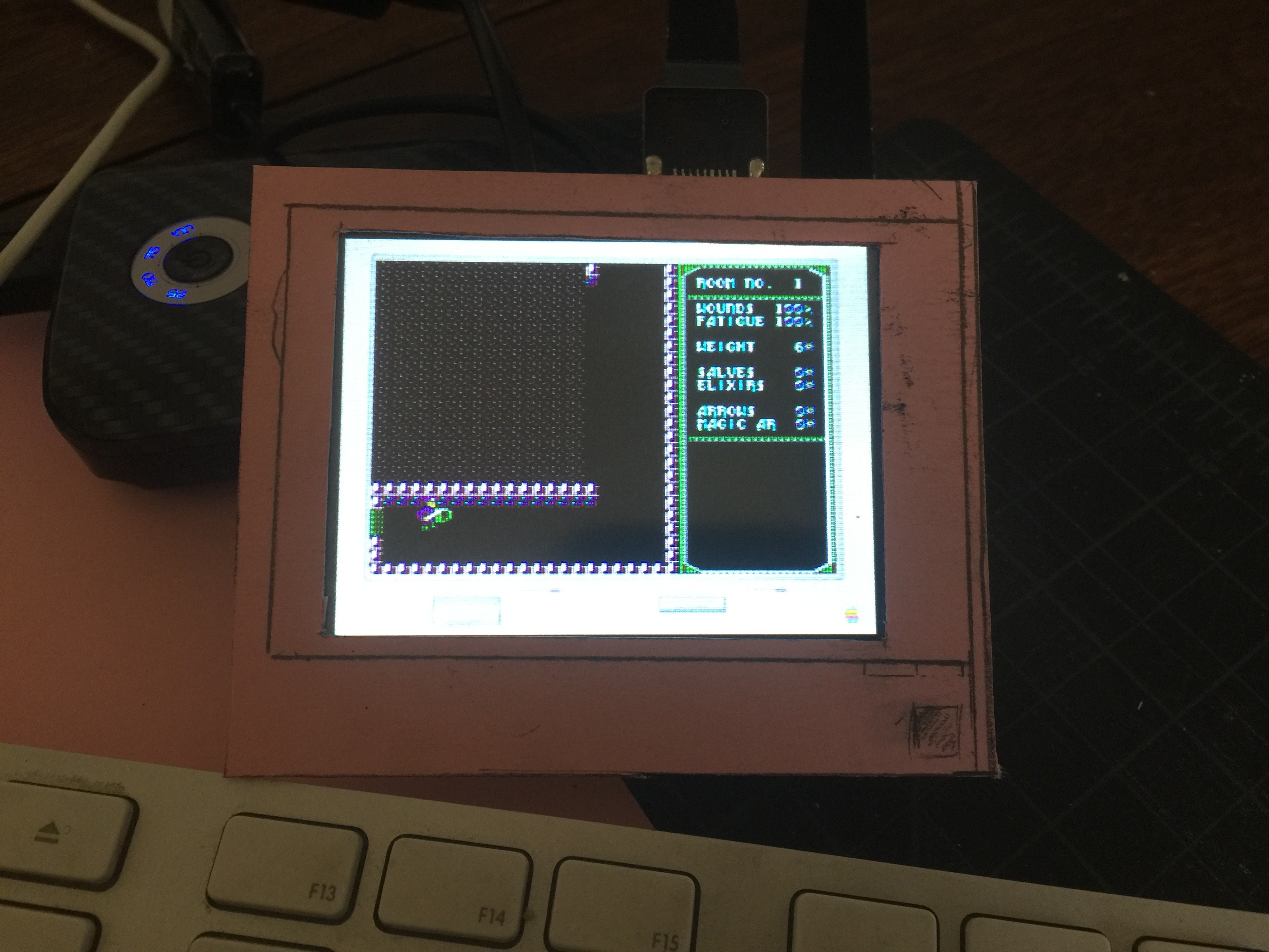
Back to the visuals, though! I wanted to see it. And here's the 3.5" scale monitor, in papercraft form.
That's the 3.5" HDMI panel, sitting on top of a Pi Zero, connected to a battery pack and a full-sized keyboard. You want to see it running, you say? Okay...
Amazingly cute.
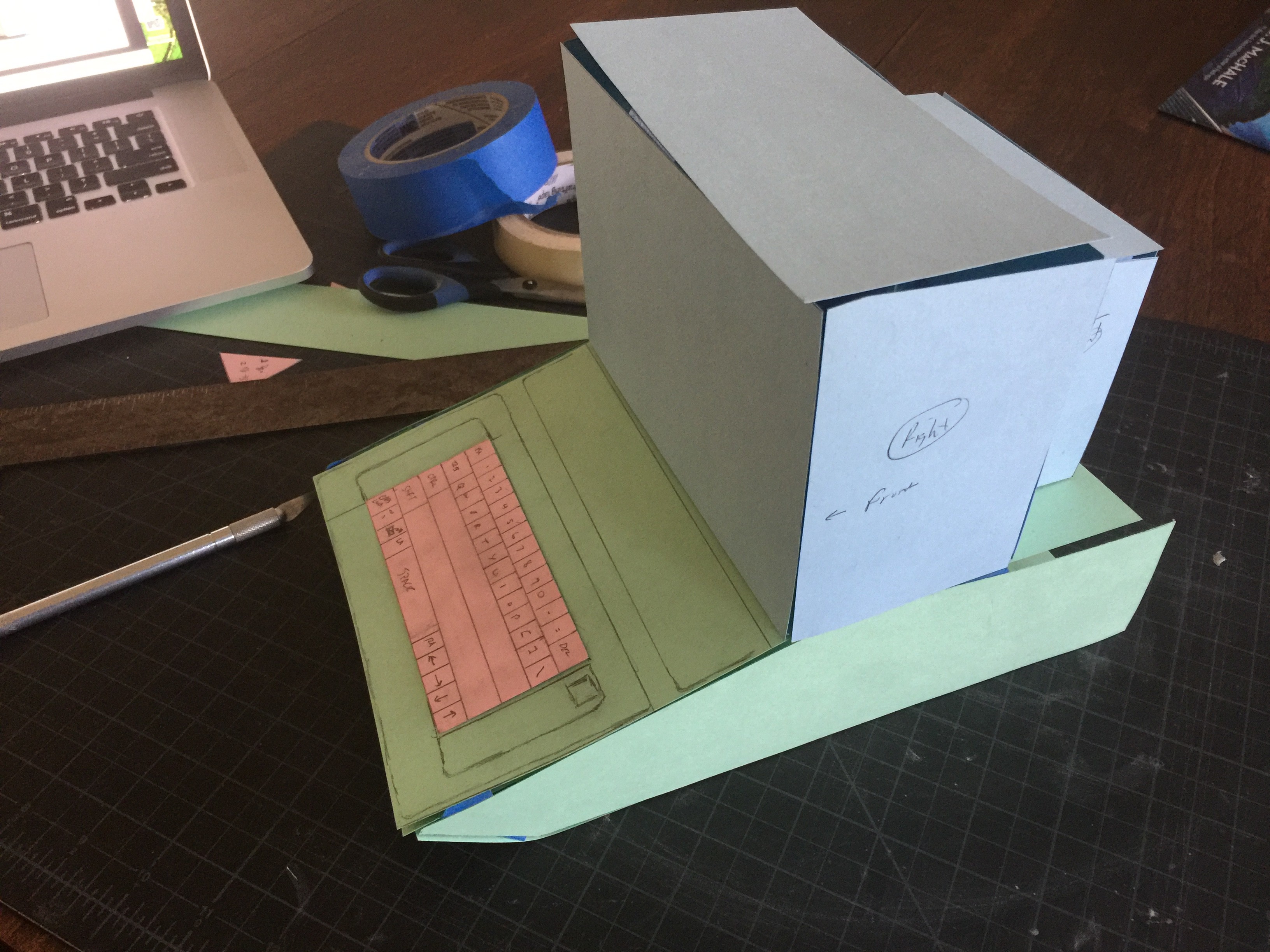
I went through the exercise of cutting out the whole monitor at that scale before I realized that I couldn't build a working keyboard at the same scale. (I didn't bother taking pictures, sadly.) Then we moved on to the version scaled around the smallest keyboard I can realistically build...
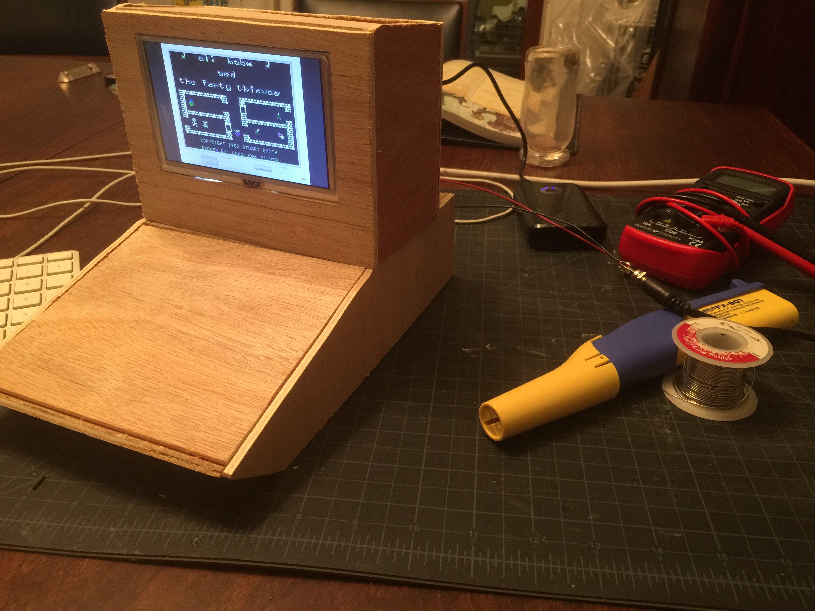
First I mocked up the keyboard, then built up to the monitor. The 5" LCD I've got is a bit small for it but I think it's workable. To get a better idea of it, I threw together a quick plywood mock-up...
Yeah, that might work. There are a lot of details I'll want to build out in that direction, but I'm pretty happy with the display. Out the back comes an HDMI input and power; this panel has no audio, unfortunately. (The 3.5" one does. Have I mentioned I really like that 3.5" display?)
So I'm going to focus on this case for the moment. (I'm starting to think that it's going to be impossible to pick one; it's probable that I'll wind up building this multiple times at different scales...) Some HDMI connectors are on order, and the weather is almost warm enough for me to start fiberglassing again!
-
Entry 18: Pi Zero W and JOSS
02/04/2018 at 16:28 • 0 commentsOne of the most rewarding moments of Aiie, for me, is turning it on. I flip the switch; the screen becomes filled with inverted @ symbols; it beeps; and then I see "Apple //e" across the top of the screen.
It's just like my original; I reached around the back, flipped the switch, and felt the static charge build up on my face since I was now mere inches away from the CRT. The screen began to glow, and beep there we go! Chunka-chunka-chunka the disk drive whirrs and we're off to the races.
I want most or all of that experience from Aiie.
When I turn on a Pi Zero W, however, what I get is a raspberry; a good 40 seconds of Linux kernel booting; and then a login prompt. Eww.
I could rip out most of the init sequence; have Linux run aiie instead of init. Systemd. Whatever. I'll still have the kernel boot time, which is fairly substantial. Sure, I could compile a custom kernel that's got the modules I need built in. Strip out the unnecessary cruft, reducing boot time. I've found a quiet boot that seems to suppress most of the messages. It's still light years away from the experience I'm seeking, though. So how do I get the kernel out of my way?
Well, don't run Linux, of course.
Enter JOSS - Jorj's OS Substitute.
I've got a working, bare-bones OS that can host Aiie with no Linux between. It needs a lot of work. There are many, many things I still don't fully understand in the BCM2835 package (that's the CPU + peripherals in a Pi Zero). It speaks out the mini UART, giving me serial; I've got the GPU initialized, giving me video; I've got one timer running successfully, giving me some timing. I've got read support working for the SD card, along with a simplistic FAT32 layer. Nice.
I don't have FPU support - or rather, I haven't verified that I've got the FPU running properly. I don't have the MMU running at all, and I haven't figured out Fast IRQs yet. But it's enough for me to get a basic Aiie boot screen up, with video refreshing properly.
Which is important, because the number one thing I'm considering right now is: how fast can I drive the display? The same question I've been asking for the last few months. Is this path going to finally give me the freedom I want to build this out in to a hardware emulation platform? And the results are not very encouraging.
The boot time is great. I'm using a bootloader to transfer JOSS + Aiie over serial here, so there's a bit of startup delay that won't be in a final version. Once the binary finishes loading and I tell it to run, it's a near-instantaneous boot.
But for whatever reason, I can only drive the JOSS-based Aiie! video at about 1 frame per second.
Clearly, that can't be the hardware. Can it? It's a 1GHz processor; it seems unlikely that video would have such an enormous performance penalty. I suppose I can find out. This thing *does* boot Linux, after all.
So time for yet another fork: the Raspbian Framebuffer fork.
Ignore the text poking out from under Aiie; I'm not allocating and switching to a dedicated VT here, so the login prompt is peeking out of the framebuffer console. I'm unceremoniously blitting all over the framebuffer directly. And I'm easily getting 52 FPS at 320x240, scaled by Linux. If I take out the delay loop, I see hundreds of frames per second. While driving the virtual CPU at full speed. This pretty definitively tells me that I'm missing something in JOSS; the hardware is plenty capable.
Why is it slow in JOSS, then? There are two major candidates. First: CPU speed itself.
When the Pi Zero boots, it actually doesn't give control to the CPU. The GPU gets control; it throws a rainbow square on the HDMI output, loads up some boot files off of the SD card, reconfigures the hardware, and then throws control over to the CPU.
The BCM2835 brings the ARM up at 250MHz. The GPU, when it's configuring the hardware, can change that. I think it's successfully changing it to 700MHz for me, which should be plenty at the moment. It's hard to tell, though; I've built a couple inconclusive test apps that try to measure the real world time delay of various busy-wait loops, and I'm not seeing the time differences I'd expect.
There's also the MMU. Having not initialized it means that I've also not initialized the caches or the branch predictor. That should be a fairly significant performance penalty.
At any rate, the direction I'm headed in isn't clear. I'm thrashing about on many different avenues trying to get a foothold on which is going to be the best.
The Pi Zero certainly has the performance I want, but the bootup process sucks; even if I replace Linux with JOSS, I think I'll have a couple second delay before the GPU hands over control.
The serial display with DMA requires external RAM, which I don't really like. And with the Pi Zero being both cheaper and faster than the Teensy 3.6, I'm reluctant to put an extra $20 of cost in to this for only 30% of the performance. Sure, the Teensy has better peripherals and a Cortex M4; but this old Arm 6's clock speed and extra RAM trounce it pretty significantly.
Building an NTSC output for the Teensy feels like it might work, but again - back to the cost. Having tasted the combination of faster + more RAM + cheaper really makes me want to go in that direction.
But JOSS still needs significant work. When it's done - or along the way, depending on how JOSS evolves - I'll still need to code all of the peripherals myself. I'm not sure I'll be able to take advantage of the Wifi and Bluetooth on the Pi Zero without massive time investment, or reliance on Linux (and the boot delay that encompasses). The USB seems massive, but achiveable. And will I be satisfied with just 26 GPIO pins? I mean, I've been totally spoiled with the 62 I/O pins on the Teensy, so I've never really thought much about how to conserve them.
None of these options feels like a slam dunk just yet, so I suppose I will just keep tinkering for now...
-
Entrty 17: A Fork in the Road
02/04/2018 at 13:01 • 0 commentsMore accurately: many forks, many roads!
It's been an interesting month of tinkering. The video output question has lead me down multiple simultaneous code forks, and I'm slowly gathering enough information to make some sort of decision. I'm not quite there yet, though... so let me recap, and recount the last few weeks.
Option 1: Figure out nested interrupts on the Teensy and keep the existing 16-bit display.
In theory, nested interrupts should save me the hassle of direct display; if I could get it set up right, then the display updates could interrupt the CPU updates frequently enough that I could reclaim the display pulse time for the CPU to run. It doesn't feel like there's much pulse time to work with, though. My programming gut instinct tells me I'd be robbing Peter to pay Paul, and while I might wind up with a small net gain of free CPU time, it would be for such a small gain that I wouldn't be able to use it effectively. Consequentemento, I haven't spent much time on this; I consider it a last-resort option at this point.
Option 2: NTSC output, from Entry 16. I think it would be possible to make a B&W NTSC driver, with nested interrupts, that works. It might buy me enough free CPU time to get the current set of Aiie features running the way I want. I don't know that it buys me enough for what I want to add later. But there is one important possible win: I would be able to correctly draw 80-column text. Right now Aiie drops a pixel in the middle of each 80-column character in order to get them to fit in 280 pixels. The result is just barely passable. With an NTSC output I'd be able to drive the output for the full 560 pixels, showing the full 80-column character set cleanly.
On the down side, I don't have enough RAM in the Teensy to do that. I'm within about 10K of its limits already; I can't double the video driver memory. Which would lead me to the same complexity I'm considering for the next option, which I think is technically superior anyway. So this is, at least for the moment, a dead end.
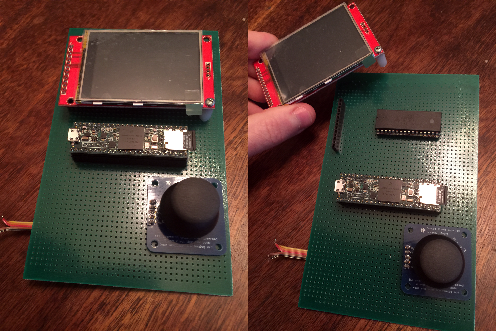
Option 3: DMA displays. I've got two 320x240 serial displays now. Ignoring, for the moment, that they're 2.8" instead of 3.2": if I can offload the work of the CPU banging data out to the LCD, then I can reclaim all of that CPU time. Unfortunately, to run DMA, I need to tradeoff RAM. I need a video buffer where I can store what's going out to the display. And, once again, I'm staring at the 10K of RAM I've got free and wondering how the heck I'm gonna be able to do that. Which brings me to this prototype:
![]()
Under that display is a SRAM chip. This feels like a bad path, generally speaking - but if I use that as the RAM in Aiie itself, then I'm freeing up 128K of RAM in the Teensy, which I can easily use for DMA. With some pretty serious side effects.
Side effect A: code complication. There's now another level of abstraction on top of the VM's RAM, so that I can abstract it out to a driver that knows how to interface with this AS6C4008. I'm generally okay with this one. There's no problem in computer science that you can't fix with another layer of abstraction, anyone?
Side effect B: performance. Every time I want to read or write some bit of RAM, now it's got to twiddle a bunch of registers and I/O lines to fetch or set the data. My instant access (at 180MHz) is reduced to a crawl. I've built some compensating controls in a hybrid RAM model; the pages of RAM that are often used in the 6502 are in Teensy RAM and the ones that aren't are stored on the AS6C4008. Even so: whenever I'm reading or writing this thing, I have to turn off interrupts so I'm not disturbed. So now I've got a competing source of interrupts; I'm back to having to understand nested interrupts on the Teensy better. This damn spectre is dogging me, and I think I see where it's going to lead; I really need to write some test programs around nested interrupts to figure out my fundamental misunderstanding about them.
I built this prototype and watched it boot Aiie using DMA to drive the display. There are bugs in the external RAM handling; assuming I iron those out, this could be feasible. But is it worth it? I'm not sure. This time I'm fundamentally limited by the RAM available in the Teensy. It's just the wrong chip for the job. Which brings me to...
Option 4: switch hardware. What I want is an ARM variant that has at least 256K of RAM; peripherals that make it possible to drive a display without wasting CPU time; enough CPU to run the basic emulator plus a half dozen timing-sensitive interrupt sources for cards that I want to emulate.
And now we're headed down the rabbit hole that I've been exploring for the last month.
After looking at a pile of different ARM chips and considering vendors, I found it really impossible to ignore the Raspberry Pi Zero W. It's a 1GHz ARM 6 with 512K of RAM for roughly $10. On a board, instrumented, with a fully functioning reference OS (Raspbian Linux).
Something about this has bothered me from the first moment I dreamt it up. I don't want this to be just another software package. The hardware is important to me. I want the joystick. I want it to be usable for the things I used to do on my //e. That was the original point; and going down this road has the possible ending of "Yeah, it's just some other software package."
I can ignore that for the moment, though, and just do a feasibility study... to add to my growing pile of prototypes...
-
Entry 16: Where Does the Time Go?
01/06/2018 at 15:46 • 0 commentsThere are a bunch of things I'd like to do with Aiie; I've got a good backlog. Things you've heard about, like Mockingboard support and a more reliable speaker-plus-video driver. Things you haven't, because right now they're totally made of unobtanium. And all of these things rely on the same underlying resource.
CPU time.
Having grown up with machines that clocked around 1MHz, part of my brain screams "it's 180 MHz; there's plenty in there for everyone!" It's got to be possible. I just haven't managed to make it happen yet.
So, for the last couple of days, I've been looking at ways to free up some CPU time.
Step 1: identify what's using all of it. Well, that's easy: it's redrawing the LCD.
Step 2: figure out what to do about it. There's little optimization to be done; I've already basically built my own LCD driver to be fast enough to work. Which means making a more drastic change of some sort. And here's where we go down several different rabbit holes until we strike gold. Or something.
This LCD panel - the SSD1289 - happened to be the largest sitting around my workshop. Since the original project was completely built out of stuff I had lying around, it was definitely the right choice. There was another option - I also have a a 160x128 pixel ST7735 display knocking around. That's not enough pixels for an Apple HGR display, though; so the '1289 won out.
When I originally got this panel, I was looking for fast video options for the Arduino Mega 2560. After a lifetime of working with PIC microcontrollers, I had just picked up a couple of Arduinos to see what the heck the hype was all about; I wanted to know what they were capable of. I used the panel for a small microcomputer build that ran a custom BASIC interpreter I'd thrown together and then set it all aside. (The Mega doesn't have enough RAM for this to be interesting; the display was too slow and klutzy for me; and there wasn't really any purpose behind the project other than generalized research.)
Given the platform, it seemed reasonable that a 16-bit data bus on a Mega would be faster than any SPI bus I could drive on that platform. And so it seemed like it would also be the best option for this project. More Data, More Faster.
Which is true, as long as I'm willing to spend the CPU on it. Aaaand now I'm not.
Yes, all of that means I'm thinking about what I could use to replace the display. And I've got two different ideas. First, obviously, would be to replace the display with a different but similar display. I've seen some great work with DMA on the Teensy that would probably fit the bill - offloading the CPU-based driver work to DMA, freeing up a lot of processor time. I definitely want to try this out. Prerequisite: a different display panel, which I don't have. That'll wait, then (a couple panels are on order; it's not going to wait long).
The other train of thought I've got goes something like this.
The Apple ][ could do this. The //e could do this with color and many display pages. My //e did this with a special video card; emulating that is taking a lot of CPU time. But all //es did this even without that card; they jammed video out their composite video port.
That's the point where the light bulb goes on and the cameras zoom in on our hero, grinning cagily.
Can I get all of this data out a composite NTSC interface? There exist small 3.5-ish inch NTSC monitors. Some of them are even rechargeable themselves, with auxiliary power out - so you can plug a security camera in to this thing for both video and power; set it up; and then plug it back in to its full-time gig. I could use one of those to double as both the display and the battery, which also gives me a built-in charger.
That sounds kind of interesting.
Of course, to do this, I'll have to do some of my least favorite circuit engineering. I really am not a fan of analog signal work. There are all these little bits of EE knowledge that are different depending on what kind of signal strength or frequency you're talking about. And they're actually really, really important.
About 15 years ago I got my amateur extra license to stretch in to analog signals a bit. I had, at the time, been playing with broadcast RF; I was teaching myself some things about transmitter and receiver design. My number one takeaway is that I don't know enough about analog design to be able to greenfield build anything more than a toy transmitter or receiver.
But this is exactly that - a toy video modulator. I think I can pull this off. I've got a couple small NTSC video panels lying around; and if I really need it, there's a 9" black and white CRT TV out in my shed (waiting for the next electronics recycling day, actually; it's time for it to go, already).
How, then, does NTSC video work? Back in the early 90s, I picked up a reference book on the subject; titled something like the "NTSC Handbook". I can still see the cover in my head. Can I find the book in my house? No, of course not. (I probably got rid of it with the first my 9" black and white CRT TVs about a decade ago.) But the difference between 1991 and now, of course, is that in 1991 I couldn't just search the internet and get all the same data, faster. (Albeit slightly less topical and curated.)
Some quick internet searches later, then, and I find an excellent reference for NTSC timing; and many sources that tell me about the 263 lines of any NTSC frame. I'm not worried about using the second 263 interlaced lines to get "full" vertical resolution; there are easily 200 visible lines in there, and Aiie is only using 192 of them anyway.
And anyone that doesn't know about the craziness in NTSC was just lost. 263 lines, but only 200 visible?
Well, each line of an NTSC signal is 63.55 microseconds long.
The first 9 lines of any NTSC signal use that time for synchronization and calibration pulses.
Then lines 10-19 have no actual data in them. In modern terms: they have the meta-data, but no pixel data.
The remainder of the 244 lines can actually be used. Sort of. Remember that this is all analog; we're spitting out a fairly messy signal, and some piece of electronics on the other end is trying to interpret voltage and timing differences to display what we're sending. The process is inherently messy - a difference in calibration on the sender and receiver would mean a difference in the display of the data.
Notably: the way this stuff was displayed on Cathode Ray Tubes means that the top and bottom lines are probably at a curved edge of the glass. That edge is generally covered up by a piece of plastic to make it look pretty on the outside. So the first few lines and the last few lines may very well be distorted or obscured, depending on the quality of your specific TV set. (The left and right edges, too; but I'm focused on the lines right now.)
It's sensible, then, to ignore a chunk of the top and bottom as suspect. Maybe they're visible. Maybe they're not. So if you need fewer lines, you pick the ones in the middle and leave the edges blank. (Or some solid color, if you're a Commodore.)
So what signals do we need to generate? Well, for black and white, we need five different voltage levels.
All of this has to be less than 1 volt. How much less than 1 volt? Well, it's messy analog. It doesn't matter too much. Let's aim for 0.75v. That'll be full on.
We also need a full off (0%); a Blank level (28.6%); a black level (34%). With those we can do simple black and white. A simple resistor network should do the trick. I don't know of any simple way to design it, without just doing an R2R ladder network of equal values and adding up bits. But I want to use a few pins as possible, so I'm going to do this differently - an uneven resistor network and some judicious application of Kirchoff.
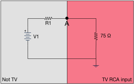
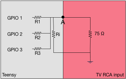
Let's start here, modeling the TV and a simple circuit to get some voltage in to that TV's RCA input...
![]()
The standard impedance of a TV's RCA input is 75 ohms. Let's ignore the meaning of "impedance" for a minute, and treat that as a resistor. Then if we have a simple circuit on the outside, where some voltage runs through some resistance; and point "A" represents the physical input to the TV; this looks like a simple voltage divider. The voltage at point A is (75 * V1) / (R1 + 75). The Teensy has 3.3v outputs, so V1 is easy; given that, we can simply calculate whatever resistors we want, and use one pin for each voltage we're targeting.
Of course, I didn't do that. It would have been too simple. I wanted to reduce the number of pins I needed - not for a lack of pins, because we're talking about reclaiming something like 20 pins from the Teensy by removing the display. No; it's more because Kirchoff circuit simplification was always one of my favorite parts of EE.
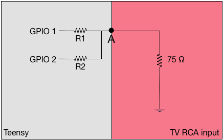
If we think about just 2 general-purpose IO pins of the Teensy – where they are either at +3.3v or +0v (ground) – then it looks like this:
![]()
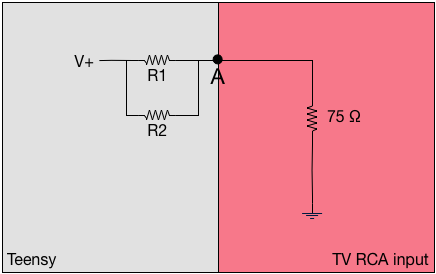
Individually, those look exactly like a standard voltage divider. But what happens when they're both enabled? Well, then it's fundamentally the same as this:
![]()
The simple formula for effective resistance of two resistors in parallel (R1 and R2) says it's R1×R2/(R1+R2). But that's the simple case if just two. The general case fir the equivalent resistance (Rv) is (1/Rev) = (1/R1) + (1/R2) + ... + (1/Rn). So we can easily calculate what the effects of any given set of resistors is in a simple ladder network: whatever bits are "on" (presenting +3.3v), we parallelize all of those pins' resistors; and then through it through the voltage divider network. Out the other end pops a value.
There's one last bit of tuning. The 75 ohm value in the TV RCA input doesn't have to be a limiting factor. We can put that in parallel with other resistors too - with side effects, but let's ignore those for now. This gives you a little more flexibility in choices for your resistors - and the model of the final circuit might look like this:
![]()
From there it's a bit of solving equations to figure out what you want the resistors to be. The difficulty, of course, is that there are a set of standard resistor values which are typically true within 10%; you can't just say "I want a 1067 Ω resistor". Instead you have to settle for a 1.1kΩ; assume that's between 990 Ω and 1210 Ω; and compensate elsewhere.
Anyway: I wrote a couple of overly complicated perl scripts to do the work for me, and came up with this set.
R1 1kΩ R2 820Ω R3 470Ω Ri 220Ω Ri of 220Ω gives an effective input impedance of 56Ω (the reciporical of 1/220 + 1/75).
The maximum voltage I'll get is 0.72v. The table of pin combinations and effective voltages/percentages of "maximum" is:
GPIO1 0.2v 27.7% GPIO2 0.24v 33.3% GPIO3 0.39v 54.1% GPIO1 + GPIO2 0.41v 56.9% GPIO1 + GPIO3 0.55v 76.3% GPIO2 + GPIO3 0.58v 80.5% GPIO1 + GPIO2 + GPIO3 0.72v 100% Those aren't particularly evenly spaced, but it's good enough for a proof of concept. It should answer the question, "can I actually draw 2-bit grayscale NTSC?" I'll use 0v for SYNC; GPIO1 for BLANK; BPIO2 for BLACK; and GPIO 1+2+3 for WHITE. The other combinations are levels of gray.
Next up is generating the actual signals.
For lines 1-3 and 7-9, it's 2.3 µs SYNC and 29.5µs of BLANK, twice each. For lines 4-6, it's 27.1 µs of SYNC and 4.7µs of BLANK, twice each. Those let the TV figure out what your voltages and timing are.
Then comes the fun stuff. From lines 10 through 263, we have these:
- The "Front Porch" - a 1.5µs BLANK;
- The Sync - 4.7µs of SYNC;
- The "Back Porch" - a 4.7µs BLANK;
- image data, between BLACK and WHITE for 52.6µs.
The width of the "pixels" (they're not really pixels, but you can think of them that way) depends entirely on how much time you spend on each one. If you make the pulses longer, the pixels are wider. You've got 52.6µs to divide up however you like.
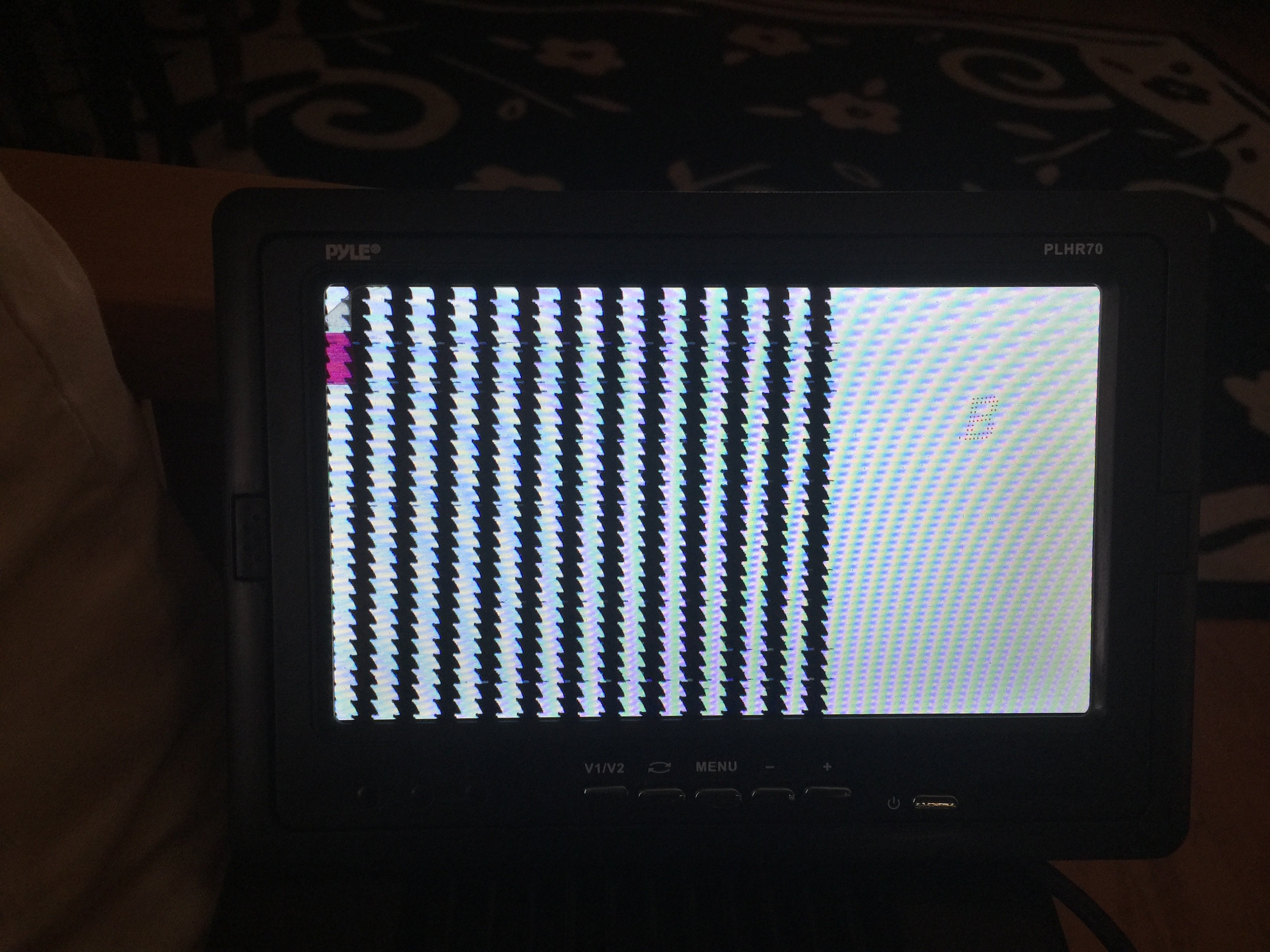
Let's start simple - 25 on/off transitions...
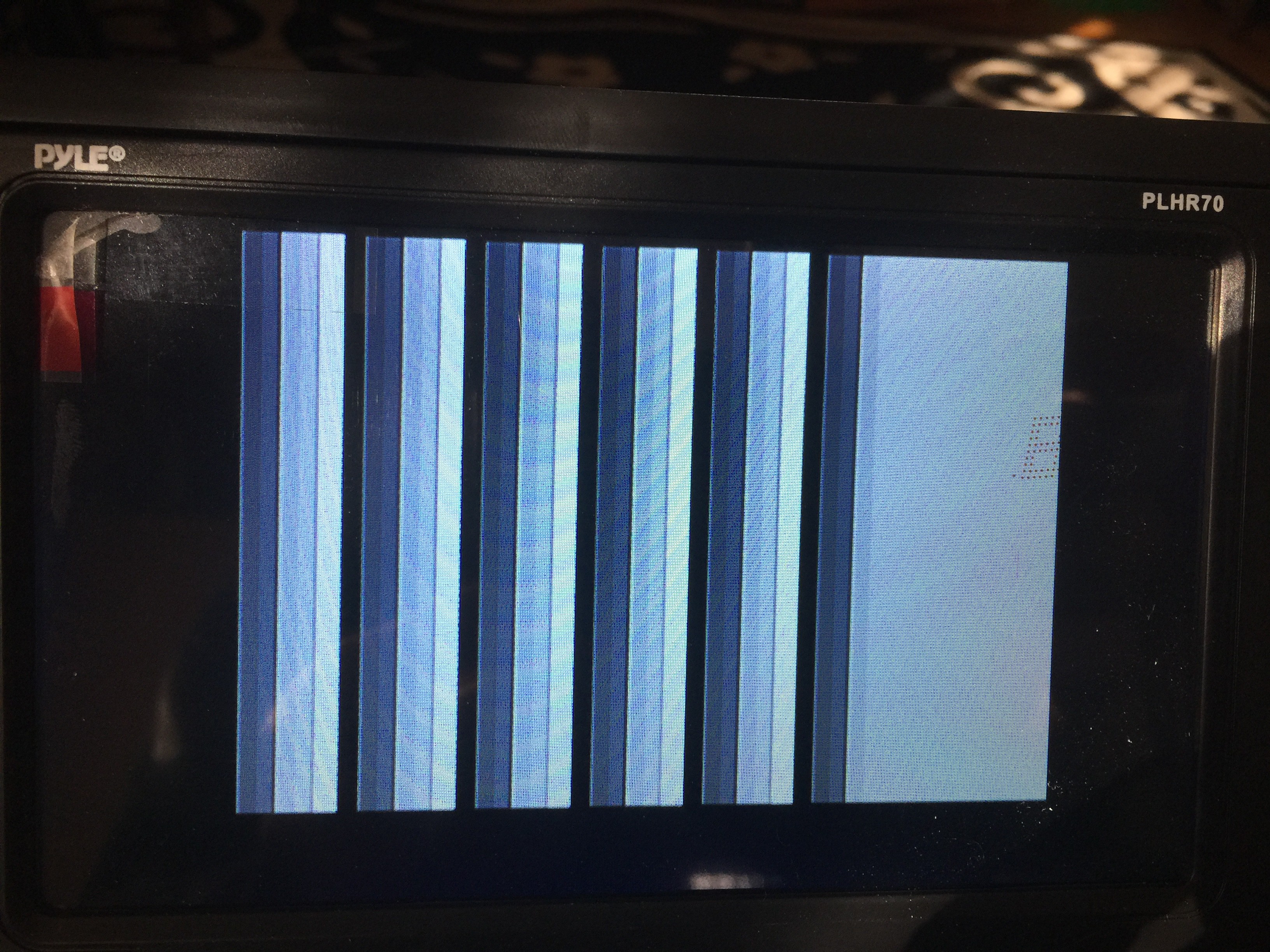
Close! The saw edges tell me that my timing isn't quite right; something is affecting the 62.55µs line timer. Find that bug and fix it, and then let's try some gray...
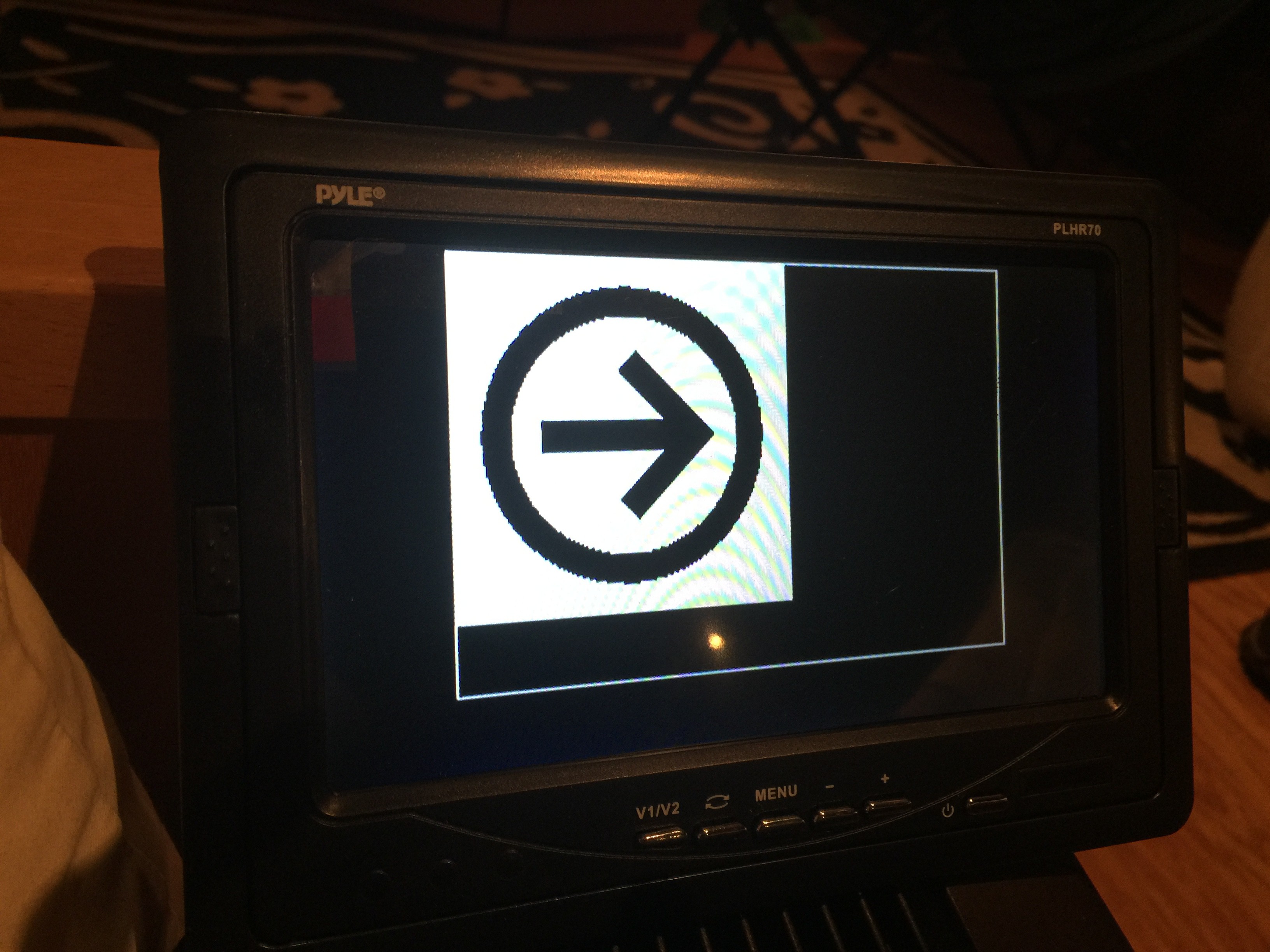
Nice. Next up, can I read from a data buffer fast enough to fill the screen with an image? Well, a quick Internet Image Search for icons, to find something simple to turn in to a C data structure; then some XPM coding, and adding a video buffer to this test project...
... and then ...
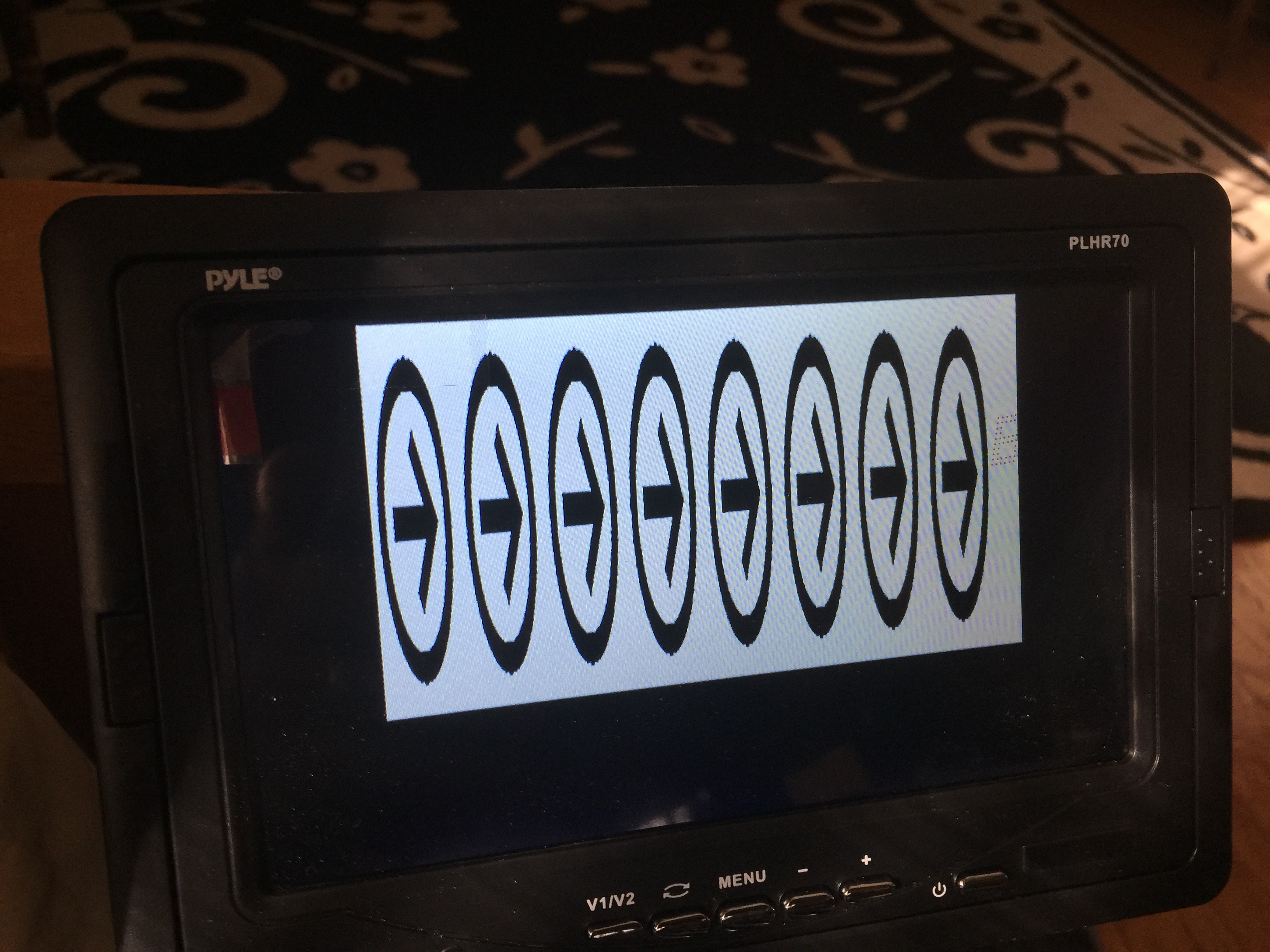
Sweet. If I turn down the delays, how many of these 160-pixel-wide images can I squeeze in to 56-ish µs?
Well, that's a pretty impressive 1280 pixels wide, plus some space at the right. (The Teensy is also 240MHz overclocked, but hey, I wanted to understand the limits.)
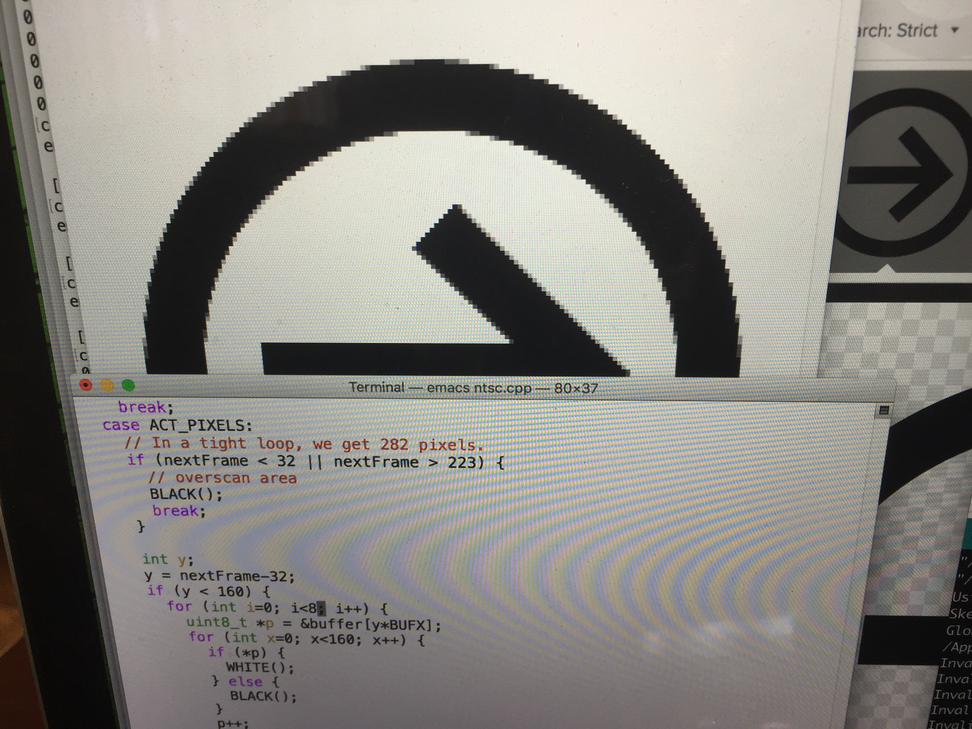
What if I marry this test project code and the Aiie! Teensy video driver? Well...
The video signal isn't quite wide enough (that is to say, the time I'm spending sending each pixel is too short), and the line sync is a little off (you can see the image wavering in spots); I'm sure those would be fixable if I wanted to go down this path any further.
Which I don't, for two reasons.
Reason 1: I'm not sure this buys me much, other than a higher framerate. The CPU overhead of driving the NTSC display is slightly lighter weight than the LCD. But I haven't started talking about color, which adds another level of complexity; and I'd still need to block for 56-ish µs to draw each line of pixels. Each clock cycle is .977 µs, so that's roughly 57 clock cycles. Right now I run the virtual CPU 48 clock cycles ahead, so the speaker has some buffered "history" to replay a teeny bit out of sync. I don't really want to make that delay longer (more RAM use and the audio will be more out of sync). I'd have to use lines 1-20 (and 213+, which I'm not using at the bottom) of the NTSC raster to run the CPU faster deliberately, and then hope the audio plays back well enough while the NTSC code is blocking the CPU from buffering more. In total it would be just shy of 11,000 clock cycles out of skew. I'm sure I could reclaim a lot of that time with nested interrupts, but that brings me to...
Reason 2: the interrupts for the NTSC timing, along with the interrupts for the CPU and Speaker, interact in ways that I'm not comfortable with at the moment. In theory, I've got four interrupts that can operate independently. They should be able to nest (where one interrupt interrupts another interrupt). I just don't understand something about how that works, because I wind up with errors like that timing issue in the video.
I'll probably spend some more time trying to understand interrupts on the ARM until the new displays arrive. Then it'll be time to play with DMA...
-
Entry 15: Testing the Limits
01/03/2018 at 15:29 • 0 commentsI left this great bomb for myself in August:
// The Timer1.stop()/start() is bad. Using it, the display doesn't
// tear; but the audio is also broken. Taking it out, audio is good
// but the display tears.

Timer1.stop();
...
Timer1.start();
Of course, I'd totally forgotten about this; when I went to play some Ali Baba, the sound was completely junked up and I didn't know why.
So what to do? Well, rip out the audio system, of course!
I may have forgotten to mention: Aiie runs on my Mac. For debugging purposes. It's a little messy; has no interface for inserting/ejecting disks; and it has the same display resolution as the Teensy. It's not ideal for use, but it's great for debugging.
The audio in said SDL-based Mac variant has never been right. I got to the point where audio kinda was close to correct and left it at that; mostly, I've been debugging things like the disk subsystem or CPU cycle counts or whatever. But now that I'm trying to debug audio, I kinda care that it doesn't work correctly in SDL.
The whole problem in the Mac variant was a combination of buffering and timing. The sound interface to the Apple ][ is simply a read of a memory address ($C030), which causes a toggle of the DC voltage to the speaker (on or off). If you write to that address then the DC voltage is toggled twice. And that's it.
For the Teensy that was fairly easy: I wired a speaker up to a pin, and I'm doing exactly the same thing. But for the SDL variant I need to construct an SDL sound channel and keep it filled with sound data. So the virtual CPU runs some number of cycles; when it detects access to $C030, it tells the virtual speaker to toggle; the virtual speaker toggle logs a change at a specific CPU cycle number and puts it in a queue. Then later a maintenance function is called in the speaker that pulls events out of that queue and puts them in to the current speaker value. A separate thread runs constantly, picking up the current speaker value and putting it in a sound buffer for SDL to play.
There's lots of room for error in that, and it turns out that my timing was bad. The calls to maintainSpeaker were not regularly timed, and were calculating the current CPU cycle (from real-time) differently than the CPU itself did. Converting that to time-based instead of cycle-based fixed things up quite a bit; removing the fundamentally redundant dequeueing in maintainSpeaker fixed it up even more. I started adopting a DC-level filter like what's in AppleWin but abandoned it mid-stride; I understand what it's trying to do, and I need to change how it works for the SDL version. Later. Maybe much later.
After doing all of that in the SDL version, I figured I'd make the same fixups in the Teensy version and *bam* it'd be fixed up faster than Emiril spicing up some shrimp etouffee. But no, I was instead stuck on the slow road of Jacques Pepin's puff pastry, where you can't see any of that butter sitting between the layers of dough until it does or doesn't puff up correctly. (For the record: I'd take anything of Pepin's before anything of Emiril's any day. But shrimp etouffee is indeed delicious pretty much no matter the chef.)
No, it took me another few hours of fiddling with this, pfutzing with that, seeing that adding delays in the interrupt routine actually *improved* the sound quality, optimizing more bits of code, and finally stumbling across my commented code above before I realized what was happening. It's the LCD.
The Teensy can run the CPU, no problem. It can run the speaker in real-time, no problem. It may very well be able to run a sound card emulator, which involves emulating something like 8 distinct pieces of hardware. But there's one thing it absolutely can't do: it can't refresh the video display in real-time between two CPU cycles.
One CPU cycle of the Apple //e, at 1.023 MHz, is 1/1023000 second (about 0.978 microseconds). One update of the video, which is 280x192 pixels, can't be faster than 280 * 192 = 53760 cycles of the ARM clock. It's certainly slower than that, but in an optimal world where there is one instruction that updates one pixel to whatever value you want, that's the absolute best case. At 180MHz, that would be 298.67 microseconds. Overclocking the CPU to 240MHz, it's still 224 microseconds. And in reality, we're probably looking at 10 cycles per pixel - so 10 times longer than those numbers.
If a CPU cycle happens in the middle of the drawing of the video display, there's a real chance that the instruction will wind up changing video memory. Which means that even though we've only drawn maybe half of the display, its contents in the bottom half (after the CPU runs) may have changed from what we were trying to draw in the top half (before the CPU ran).
That's what the time bomb above was for. It's a lock: "don't run the CPU while we're updating the display." That ensures the display is whole. And with CPU buffering - running multiple CPU cycles at once, and then waiting until real time catches up to us before running again - it all averages out. It's not obvious to the user that the CPU is running too fast, then paused; then running too fast, then paused. The delta is measured in milliseconds. But when you add the *speaker* to that, well, now you'll notice. You can't run the speaker too fast and then too slow without hearing it. The result is a chirpy high-pitched version of what you should be hearing - where the pitch drifts a little up and down depending on how regularly we're being called.
So there are four fundamental choices.
First: prioritize the display. That's what the code above does. It ensures that the displayed image is a whole image from the video buffer. Audio suffers.
Second: prioritize audio. That's what the code *did* before I put the stops and starts in. You wind up with good audio, but the video "tears" - you get half of one image and half of another. In Skyfox, you'd see this as half a cloud.
Third: put the audio driver in the video loop. I'm really hesitant to do this. It would allow both to work, but it's architecturally inelegant.
Fourth: add a second interrupt that just runs the audio queue. Then the audio queue can run in decoupled from the CPU, so the video draw won't care.
I think that last one is probably the best way to handle it eventually - but it's going to be messy. I need to be sure that the two interrupts can coexist without breaking each other, and I need to be sure Aiie has enough audio queue RAM to store the audio data. It will take some experimentation to figure out the logistics. I also probably want the audio interrupt gets a higher priority than the CPU interrupt - so that the audio queue can interrupt the CPU while it's running, because the CPU run might be running multiple cycles ahead of time. (Right now there's a realtime stop in the virtual CPU: if it detects a change on the speaker pin, it exits immediately instead of running more cycles. But that doesn't actually solve the problem; it just shoves it off to the next time the virtual CPU is scheduled to run!)
So for now, I've added an option to let the user choose option 1 or 2. Now to start coding up option 4 to see if it's feasible...
-
Entry 14: Disks Disks Disks
01/03/2018 at 13:56 • 0 commentsAs predicted, I came back to this project in December. The github code has been updated a few times over the last couple weeks, and here's what's happened.
Having left this on the shelf for so long, I'd forgotten where I'd left everything. So I started with "what do I want the most?"
Answer: hard drive support.
Back in the 80s, while I was in high school, I worked at a software store. (Babbage's, for any of those that might remember it.) While I was there the ProDOS version of Merlin (a 6502 assembler) was released. I bought myself a copy and started writing things. I noodled around with ProDOS - both the external command interface and the internal workings of its disk system. And I have images of a couple of my development floppies.
I'd love to consolidate all of that to a single hard drive image.
So, looking around for ProDOS hard drive support, I stumbled across the AppleWin implementation. One of its authors wrote a simple driver to emulate a hard drive card that ProDOS will use. So I pulled their driver and wrote code in AiiE to interface with it. All told, it took about 6 hours to get this working (3 hours to write the code, and 3 hours of constantly retracing my steps to find the typo while taking cold medicine, ugh).
Well, that was easy! What's next?
I guess I'd like to boot GEOS. Not for any particular reason other than I had run the first version of GEOS for the Apple //e back in 1988. The disks won't boot, though; they give me various system errors. Why, exactly? Well, it's all in the disk drive emulation.
The Disk ][ was a favorite research topic of mine back around 1988; I was fascinated by the encoding of data on the disk in particular. Which makes all the work on the disk emulation so much more enjoyable! Instead of being in the Apple //e and trying to read and write nibbles of disk data, I'm in a virtual Disk ][ trying to send Aiie data that /looks/ like it came from a floppy controller!
My first pass of the floppy controller code was a mishmash of approaches. I looked at how other people had implemented theirs and cobbled together something that looked like it worked. Which lead to code bits like this:
// FIXME: with this shortcut here, disk access speeds up ridiculously.
// Is this breaking anything?
  return ( (readOrWriteByte() & 0x7F) |
            (isWriteProtected() ? 0x80 : 0x00) );
Now, that piece of code totally doesn't belong there. I had it jammed in the handler for setting a disk drive to read mode. I think I'd accidentally put it in there while writing the code the first time around, noticed the performance improvement, and left it there with the comment for future me to puzzle out.
Rather than starting on this end of the thread, I figured I'd gut the rest of the disk implementation and see what could be cleaned up. First up was the stepper motor for the disk head: a simple 4-phase stepper, where each of the four phases can be energized and de-energized by accessing 8 different bytes of memory space. The drive actually steps in half-track increments, which some disks used as part of their copy-protection schemes; but that's not really useful to me, so I'm only supporting full tracks (as do all of the emulators I've looked at so far).
My first attempt kept track of the four phases and which was last energized; and then divined the direction the head was moving. If we went past "trackPos 68" (which is to say track 35, because 68/2 is 34, and tracks are 0-based) then the drive was bound at 68.
I decided to rewrite it. The first rewrite kept distinct track of the four magnets, so it could tell if something odd was happening ("why are all of these on?"). But again, that's not really useful to me, and I kept confusing myself about the track positions. So the second rewrite keeps track of the current half-track ("curHalfTrack") and only pays attention when phases are energized. It assumes that the de-energizing is being done properly. Then a two-dimensional array is consulted to see how far to move the head, and in which direction, based on the previous stepper and the current stepper energized magnets. The proper bound (at least, I'm going to say it's the proper bound) for the end of the disk is 35 * 2 - 1 = 69 half-tracks, rather than 68; and with that in place, I still got nothin'. GEOS refuses to boot.
The hint of what was wrong was right in front of me, though. Just before it triggered an error, the second disk drive lit up for a moment. Presumably it's probing to see what's in the second drive... and then it dies. Which is all because the track is cached, and my caching was buggy.
Why do I cache the track? I'm glad you asked! This gets in to that whole disk encoding thing.
The Disk ][ couldn't reliably read more than two consecutive zeros from a diskette. That means you can't just store data on it; you have to transform the data in to a stream that never contains more than two consecutive 0 bits; and then write that to the disk. So while the diskette might have a stream of $00 $00 $00 $00 bytes when it gets through the Apple RWTS disk subsystem, it's actually stored on disk as $96 $96 $96 $96 $96 $96.
And more than that: there's no physical start or end of a sector on the diskette. To read "sector 0" the head moves to track 0, and then the computer starts reading. It looks for magical headers and footers that encapsulate meta-information - specifically, what track and sector you're on. "$D5 $AA $96" <volume ID, track, sector, checksum> "$DE $AA $EB". Then "$D5 $AA $AD" as a prolog for the data section of this sector, followed by those encoded values above; finally terminated with "$DE $AA $EB". If the header said it was, for example, sector 2 then we keep reading; we didn't find sector 0 yet! The disk spins and we find whatever's next on the diskette.
Of course you need to be careful that you don't pack the data in too tightly, or the CPU will miss some of it while it's processing. And, since drive speeds vary slightly from physical drive to drive, you could format a disk in one fast drive and then try to write a sector in a slower drive, overwriting the next sector header accidentally. So there are also junk ("gap") bytes in the stream.
And that's how a simple 256-byte sector turns in to a variably-sized mess of goop.
Looking at it from the hardware perspective: when Aiie is presenting Disk ][ data to the OS, it's being asked for one byte at a time. Which means that Aiie needs to know which encoded byte it's on. Since the sectors are in a specific order on the disk, it's easiest to prepare a whole track and then just present bytes out of that buffer.
Now you know why there's a whole track buffered. No, it's not necessary; we could do a sector at a time, and add some clever counters for gap bytes and whatnot. Maybe in the next iteration; it could save some memory. But I'm not dying for it just yet. I made various adjustments to the gap handling, though, mostly because I was troubleshooting and had no idea what I was looking for; and I removed that hacky hack shortcut code that doesn't belong there, because I was cleaning up while debugging.
Back to the problem: when you switch drives, I wasn't properly clearing the cache. We wound up switching to drive 2, which got some garbage cache because there's no disk in it; and then switching back to drive 1, where these garbage was still hanging around, but the cache flags said that drive 1's cache was still valid for the track it was on. Fixed that up, and GEOS tries to boot.
I say "tries to" because it really seemed to just hang.
So I popped back in a virtual disk image I'm very familiar with: Ali Baba, the game that inspired the name of Aiie. While loading it shows the track and sector that it's reading from onscreen. It's a great way to quickly assess how the disk drive is performing. And the answer is that it was performing *very* badly. It made progress but very slowly.
I spent a few hours reading through the code and verifying that the returned bytes were correct. And then I spent about an hour reading parts of "Understanding the Apple //e", Jim Sather's amazingly complete book - one of three serious references I turn to when I feel like I'm missing something. And there it was, hidden in chapter 9 - hidden well enough that I can't find it again as I look right now. Somewhere in the disk nibblization piece is a comment about how a byte is filled - how the disk controller might return something without the high bit set because it's still in the process of reading the data from the diskette. Along with comments about how the logic sequencer finds valid data, this got me thinking: am I returning data to the Apple too quickly?
Well, that's easy to test. I threw in a flag that would only return a valid byte on every other read attempt. And sure enough - as soon as I did that, the reads were amazingly fast. Faster than they were with the hack above.
Why the heck does the machine try to read that quickly, if it can't process that quickly? No idea. Probably something to do with the nature of speed differences in Disk ][ drives. But now, finally, I can see GEOS boot up!
Of course, I can't really use it for anything because it needs a mouse...
-
Entry 13: Assembly of the Things
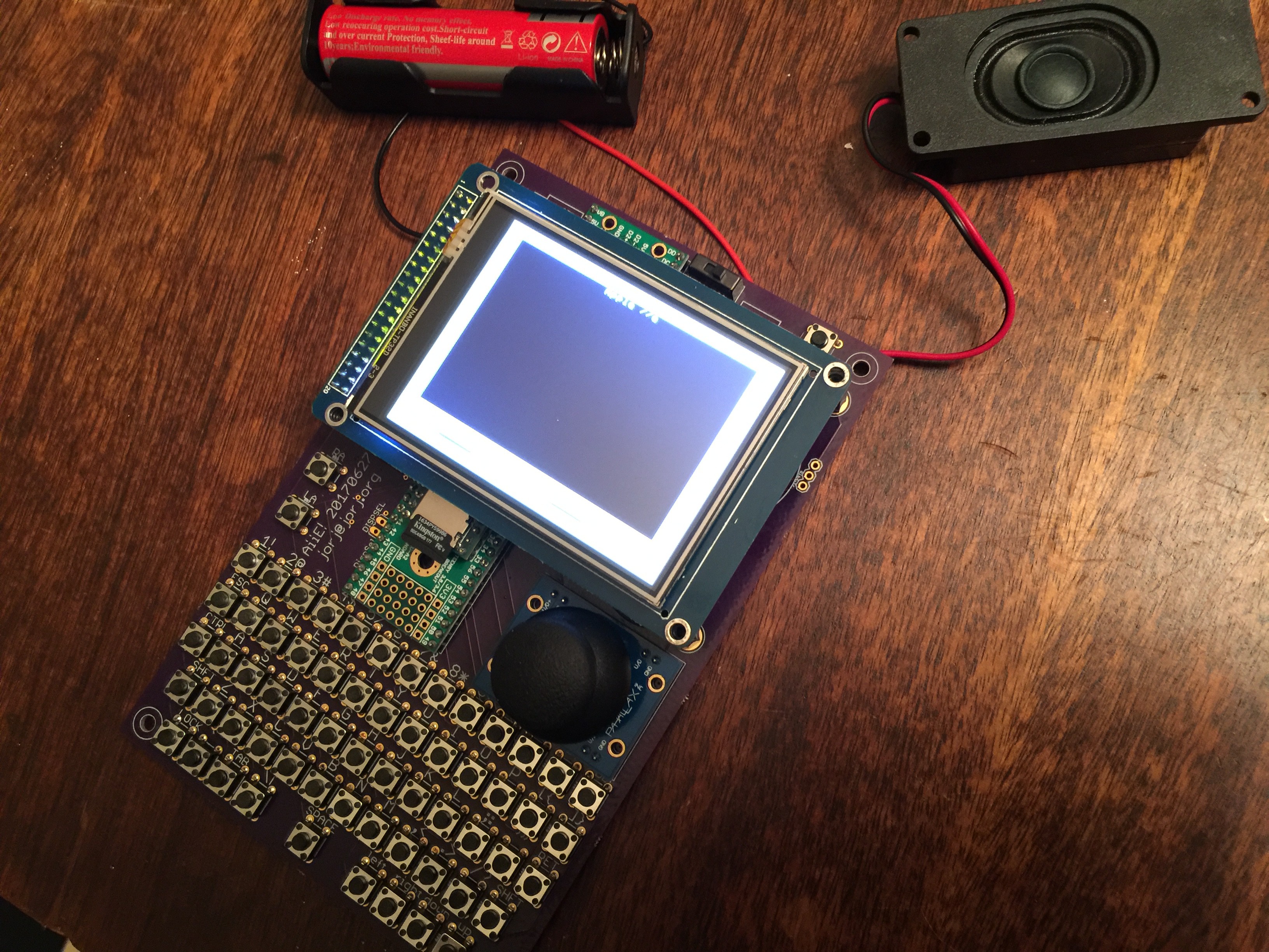
07/13/2017 at 10:37 • 1 commentI didn't know it was possible to have a first-run PCB that actually worked.
The silk screen label error is the only one I've found so far. The joystick axes are reversed, which I thought I was probably doing when I wired it up; I intentionally didn't bother checking. And I haven't verified the voltage divider on the analog input to check the battery level (it didn't work correctly in the original prototype, so maybe it's also not working here).
The Teensy is behind the LCD, as you can see - which means the MicroSD is much more accessible (it's no longer jammed up against the joystick).
I picked a random speaker from Adafruit that looked like it would be reasonable, and it's fairly loud, so I'm happy with that choice. It and the battery are now double-sided-taped to the back of the PCB.
Next up is some software cleanup. I left the software in an odd state; I was implementing real-time audio interrupts for better sound card support. To get that, I sacrificed video quality that I'd like to get back now. And there's at least one error that Jennifer found in the original code when she tried to compile it with a newer version of the Arduino environment...
-
Entry 12: The Things Start Arriving
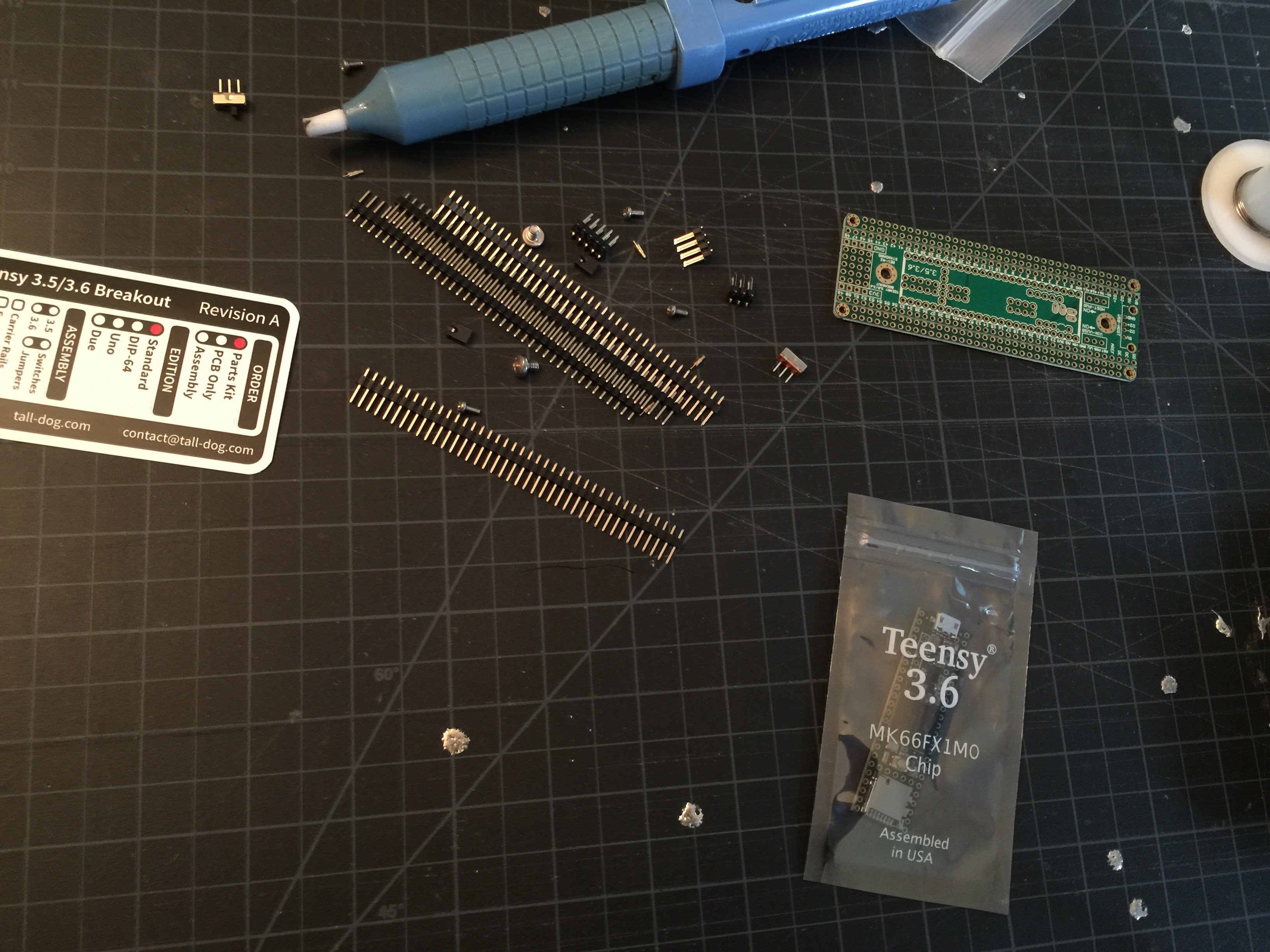
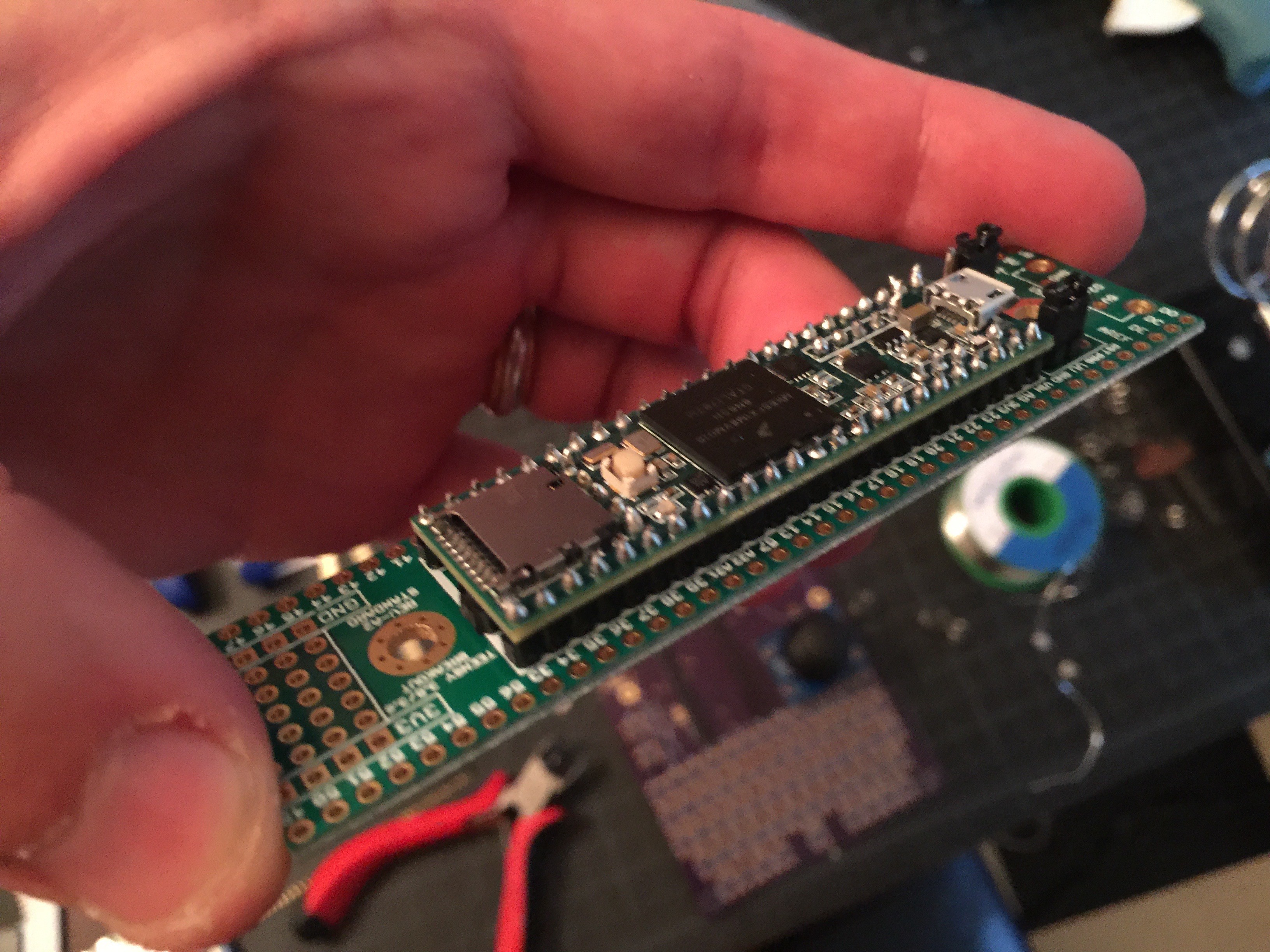
07/11/2017 at 04:10 • 0 commentsJust about everything arrived in the last couple days. A couple of Teensy 3.6es came on Saturday; the Tall Dog Teensy 3.6 breakout board arrived today. (I decided that I'd like people to be able to buy those pre-assembled, if they're not up to the soldering, so we're trying a version that uses the adapter board. We'll see how that works.)
![]()
About 45 minutes to slowly mate the two...
![]()
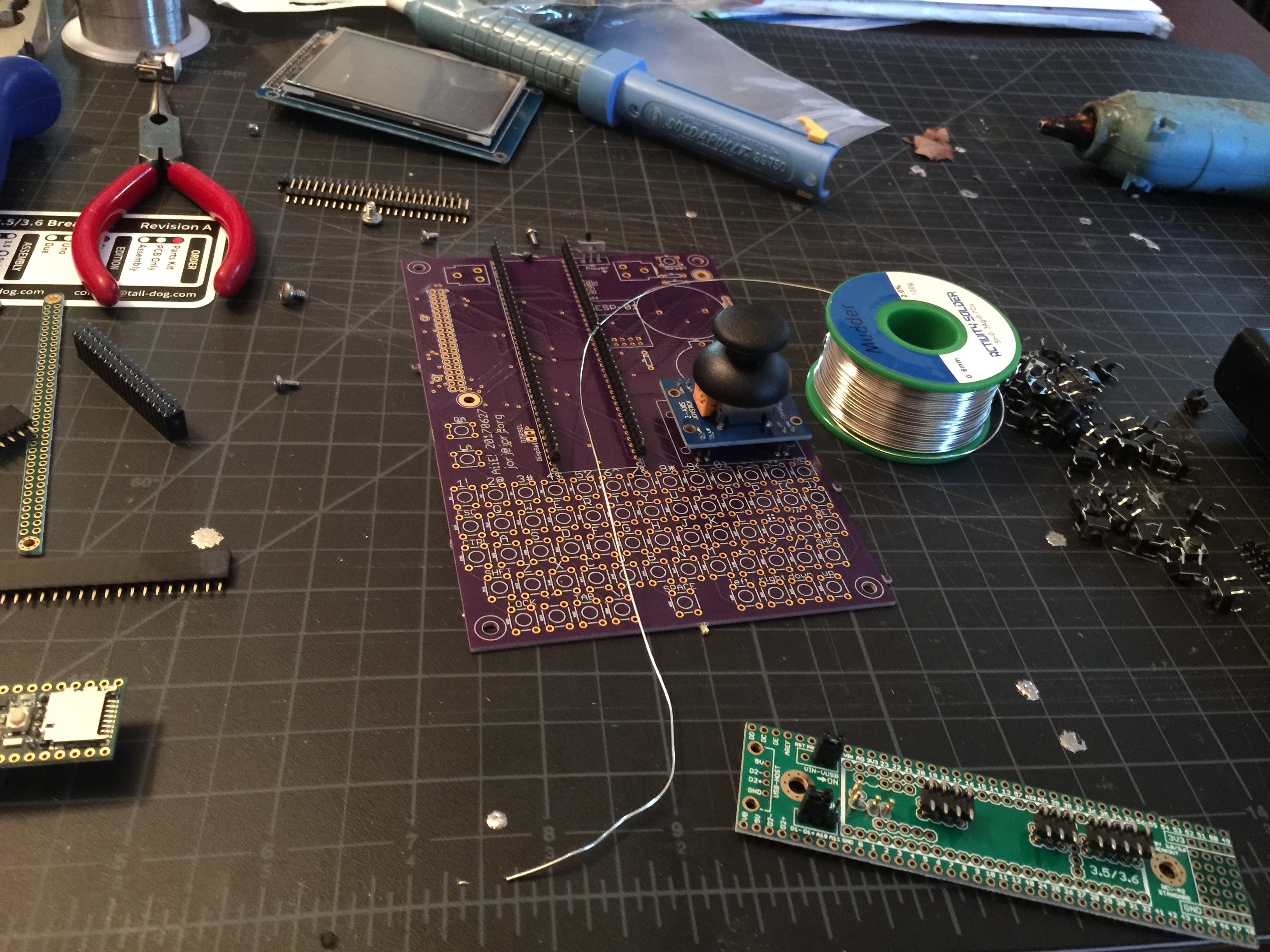
And, bless my luck, the OSH Park PCBs also arrived today!
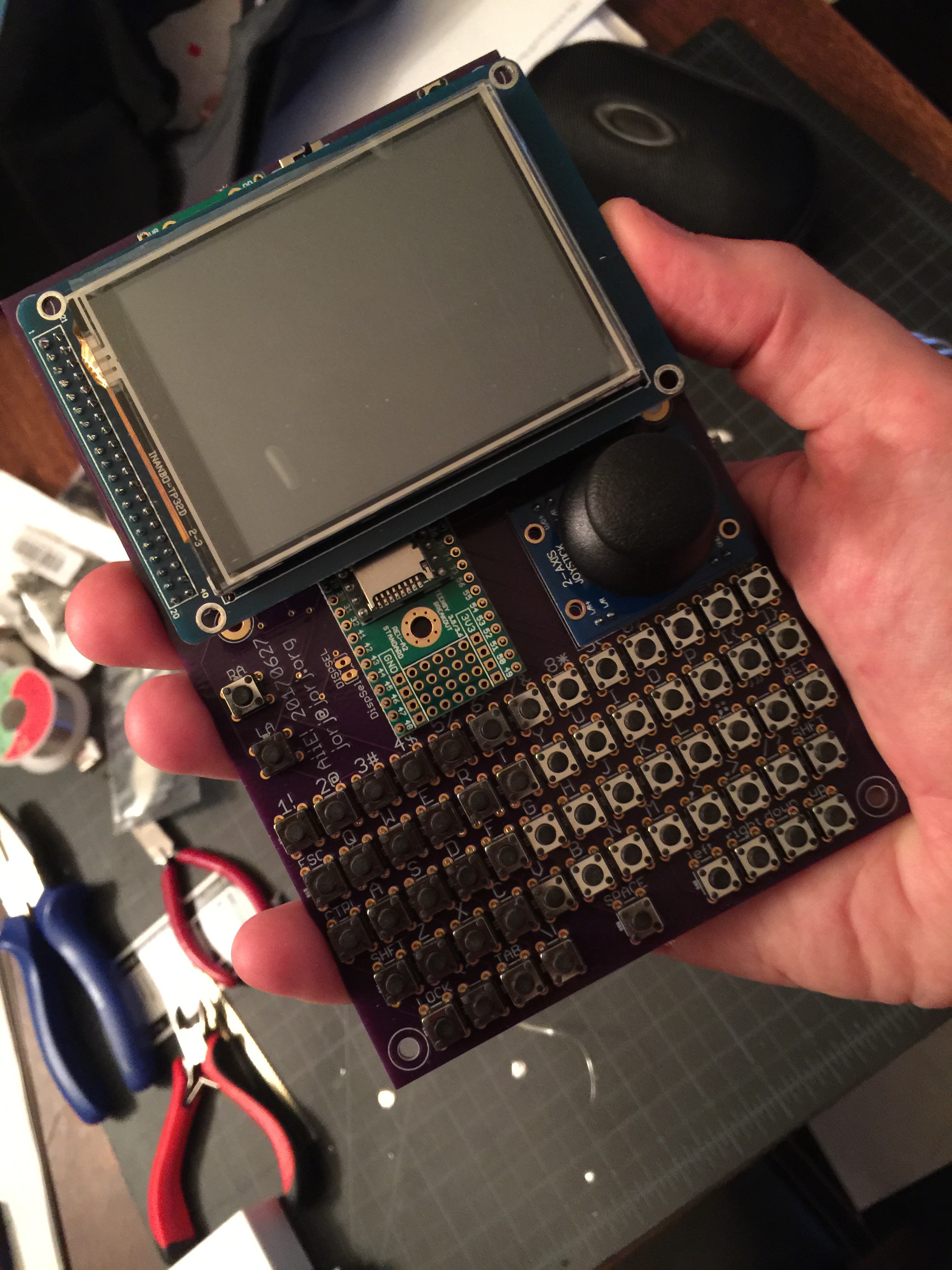
So far I've found only errors in the silk screen layer. The speaker and battery labels (on the back side of the PCB) are reversed; a few of the labels for the keyboard are a bit too big and are cut off oddly. The drill holes for the display, and the custom part I made for the joystick breakout board, line up perfectly. And the joystick appears to completely clear the display and Teensy, no fouling at all.
Quickly, then! Let's throw all the components on the PCB and see what it looks like...
Oooooh. Pretty.
Now, the Teensy is fairly tall; I'll need to raise up the display higher than normal to accommodate. So we'll have to wait a few more days: some 16mm standoffs and an extra tall 2x20 pin header are on their way from Adafruit. Being this close to New York, their parts arrive hella quickly, so maybe I'll be able to solder this all together on Thursday...
-
Entry 11: Prototype Board is at OshPark
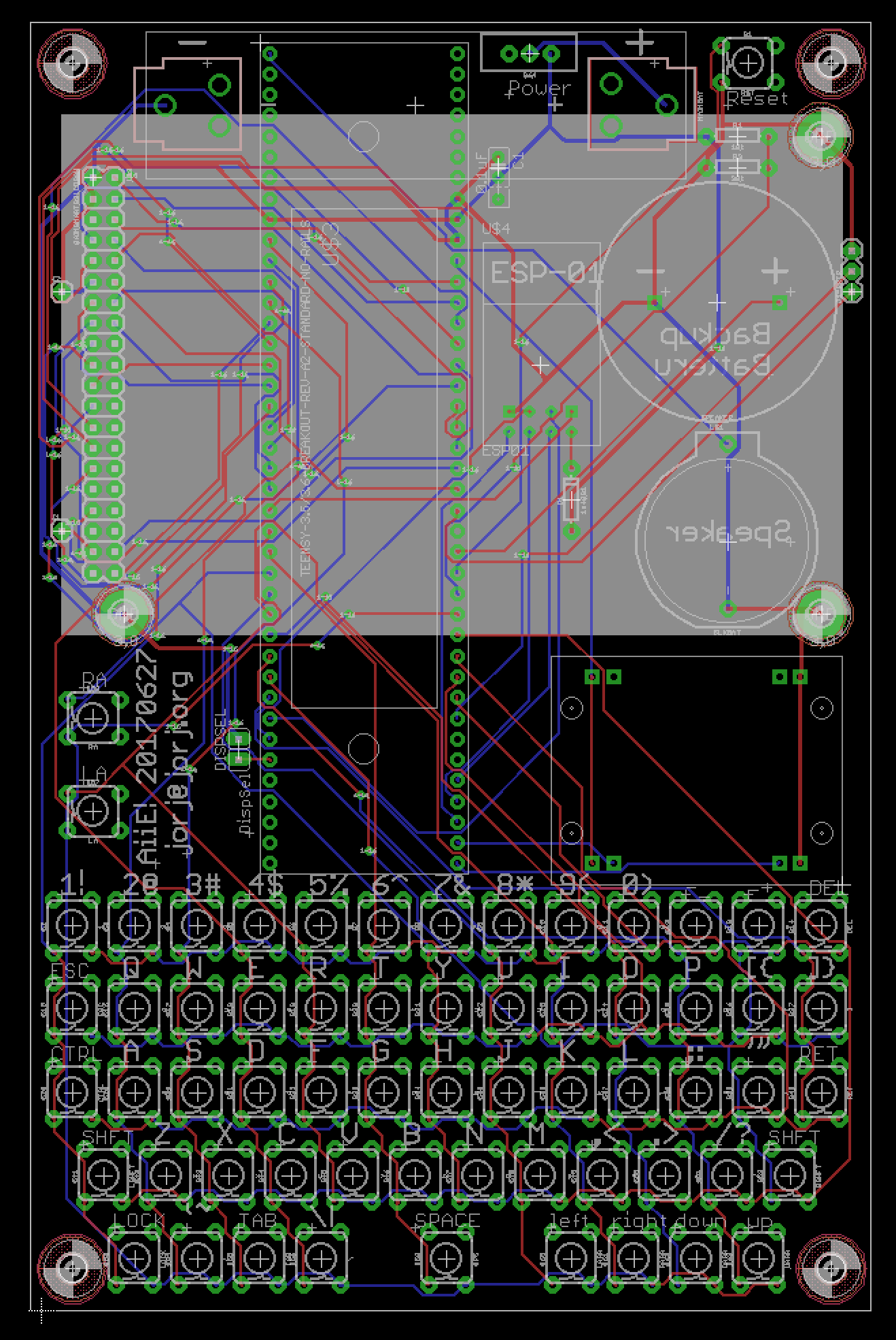
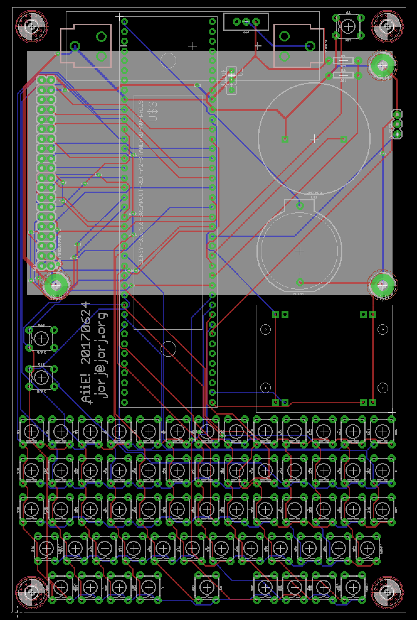
06/28/2017 at 10:20 • 0 commentsIt's still a bit of a mess, and I have to do some coding to bring it in line with the latest schematic, but...
![]()
![]()
... it's assigned to a panel at Osh Park.
One interesting tidbit came up during the wiring cross-check - the display that Jennifer bought from eBay has its pixels in an odd order (something like 1 4 3 2 5 8 7 6).
![]()
With some fruitless digging in the datasheet and then more fruitful searching on the internet, we found a similar problem from someone else that was resolved with an initialization change; it traces back to one specific bit:
LCD_Write_COM_DATA(0x0001,0x393F);
Weird, but here's the proof...
Anyway - since there are obviously at least two different versions of this display, I figured I'd throw in a configuration jumper on the first prototype board ("DISPSEL"). Easy enough to read a pin on startup and decide how to initialize based on that.
Next problem: while building out all of the key labels on the silkscreen layer, I found that I'd misplaced some of them (whoops); and that the connector for the display was rotated 180 degrees (double whoops). After fixing those, the autorouter couldn't route all the traces (triple whoops - I feel like I should have bought a lottery ticket).
So: J1 and J2 now exist to provide path for the LCD voltage. I also remember - vaguely, too many projects between then and now! - having seen the display flagging very early in the battery discharge cycle, probably because it expects 5v and I'm giving it whatever's coming off of the 18650 (nominally 3.7v, but up to 4.2v when fully charged). So this also gives me the chance to play with a boost circuit here, I suppose. Two birds killed with one stone?
Lastly - I had one more surprise hiding in my hand-wired prototype: an nRF24L01 board. I was toying with using a SLIP connection back to a machine in my office for some Internet connectivity... but have changed plans, substituting an ESP8266 ESP-01 module instead. :)
No idea when I'll get that coded or wired; also no idea if I'll get it to work. But it's there and if it does what I want, all the better...
-
Entry 10: Publishing...
06/24/2017 at 21:51 • 0 commentsSeveral people are interested in building these. Interested more than is probably healthy, which also describes me in my initial build for this thing too. And then there's the pile of hoops I'm jumping through to publish this and build a better prototype, which is *definitely* not healthy. :)
And step 1 of that would be to draw up the schematic.
I've not really used Eagle in years. I've made several small devices, used BatchPCB (when it existed) and OSH Park to manufacture them, and enjoyed the results. All except the part where EAGLE is designed for engineers, by engineers, without any serious thought about UI. It's truly one of the most awful UI experiences - second only, I think, to AutoCAD. So when I read that EAGLE had in fact been bought by AutoDesk, I knew I was in for a world of hurt.
Well, maybe I didn't give them enough credit. They fixed a really annoying UI problem with trackpad zooming from Eagle 7. So that's an improvement. And many of the icons no longer look like they were drawn in MacPaint in 1990. But then we get in to this modern trend of "let's charge a monthly subscription fee! That's better for the consumer!" bullshit.
I want to buy a piece of software and use it until it no longer meets my needs. I mean that either there's a new version that does something better, which I explicitly want; or it doesn't run under the OS that I'm running on my machine, because I decided to upgrade my OS. I'm still using Lightroom 4, for example. It meets my needs, it runs fine on my machine, and I have no interest in upgrading. Yes, there are new features in Lightroom 5 that are fantastic. Yes, Lightroom 6 probably improves on that a lot. I don't want those things yet.
So why, then, would I want to pay a monthly subscription to be able to use software? What if I'm on vacation and decide I want to noodle around with schematics while I'm on a plane and disconnected from the Internet? What if my interests have bounced away from software X this month, and to software Y? How much of my life do I now need to spend managing which licenses I've paid for this month, and what that does to my saved files when I accidentally open them or forget to renew a subscription?
Or a more real possibility: what if I'm up at 3 AM and decide I want to design a PCB that's roughly 7" x 4"? I need to buy an upgraded license for Eagle 8, and then WAIT THREE DAYS FOR THEM TO FIGURE OUT WHY MY CLOUD ACCOUNT DOESN'T SHOW THE UPGRADED LICENSE.
Thanks, chuckleheads. I appreciate that your cloud service saved me absolutely no time. Your model is not what I want, and is not better for me. It's more frustrating.
But at least it's going to save me some money. Maybe.
I was ready to shell out the Pro license fee for a full upgrade of EAGLE. But now I can pay $70 for a single month, design this thing, and drop the license, reverting to the educational license that I get because I work at a University. Maybe. We'll see if they're able to do that without the license manager barfing again.
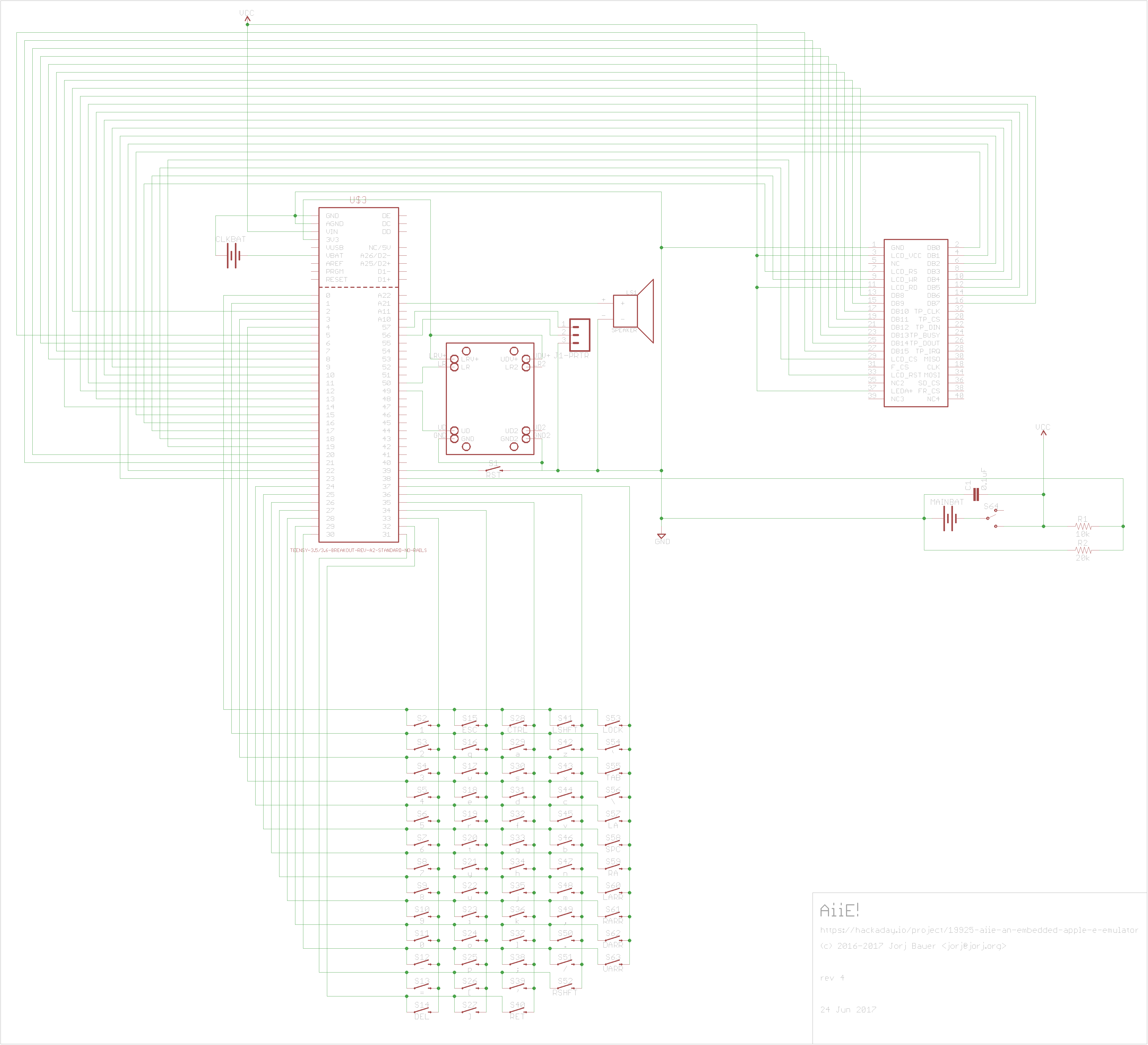
Okay, rant over - I've got a first draft of the Aiie! schematic. It's a doozy; I've drawn it without using bus simplifications...
![]()
The Teensy 3.6 has been replaced with the Teensy 3.6 on a breakout board from Tall Dog on Tindie. This was something that a very devoted Apple fan brought to my attention because she'd found them and was planning to use one for her own build. (Thanks, Jennifer!) It saves folks the trouble of soldering the pins on the back of the Teensy, at the cost of an extra $15 or so and a serious lift in board space required. Meh, good enough for now.
There are probably mistakes in my drawing. I haven't yet validated this. I'm pretty sure I mixed up the joystick X and Y axes, at least.
The aforementioned Jennifer is wiring up one by hand; assuming she gets good results, I'll submit the PCB to OSH Park and do another build myself to see how it works.
At a cost of $125. Just for the PCBs.
Yep, this board is not a teeny little thing. It costs a bundle to have fabricated as a one-off. Or, more accurately, a three-off; that's the minimum order over at OSH Park. Previous experience tells me they'll be awesome, assuming that I've gotten the schematic right.
Now: a quick word about changes from the first prototype.
I'm sticking the Teensy behind the display. And it doesn't really fit there well; which means the display will probably need to be further raised off of the main PCB. I think it will be a cleaner build this way, without the Teensy and display fouling the joystick's path of motion.
![]()
... but I'm guessing about that. The joystick is also still on its original Parallax board here, meaning it can be raised further relatively easily if it needs clearance.
The biggest compromise, however, is that I let the autorouter do absolutely all of the wiring here. I've run out of patience with EAGLE. Here's hoping that it didn't totally break, for example, the ground connection through the 3 screw holes for the display. (The fourth hole seemed ill placed because of the battery, so I decided to drop it.)
Time will tell! Here's hoping that Jennifer's attempt lights up her LCD with some Apple //e booting screen goodness, and then I'll submit these PCBs to OSH Park for some more testing...
 Jorj Bauer