agp.cooper
-
Third Test Paddle
06/12/2017 at 12:31 • 0 commentsThird Test Paddle
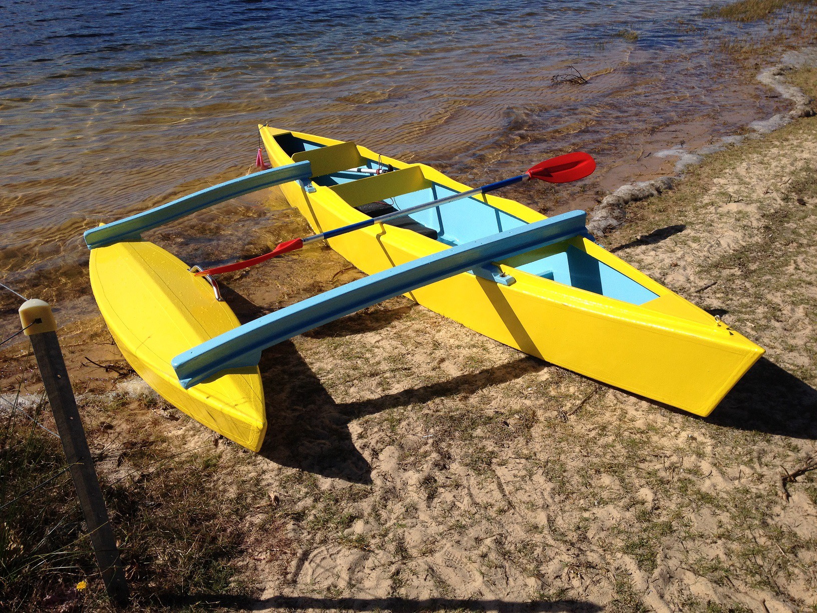
After cutting off the rear cross-beam I went for a third test paddle. This time I paddled to a near by bridge and back again (2.8 km return). I am far from being a young, fit and an experienced canoeist, took me 39 minutes or 4.3 km/hr. The canoe hull speed 8.5 km/hr (you would need an outboard motor to go any faster!), so plenty of room for improvement. My target is 6 km/hr so I need to do it in 28 minutes. It will take me a while to get to this speed no doubt.
The weather in Perth Western Australia even in winter is mild the average maximum is about 19 degrees C in June. Today it was 19 degrees C when I arrived and about 22 degrees C when I left. The down side is that the UV index down here is pretty extreme. You need to acclimatise to the sun or you will get burnt to a crisp!
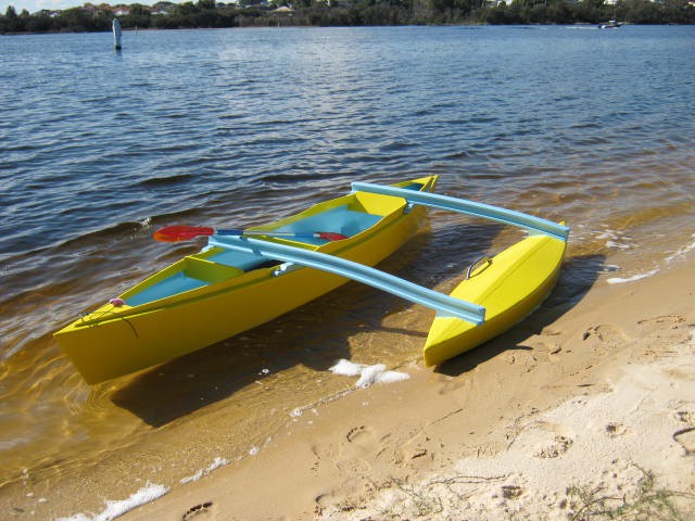
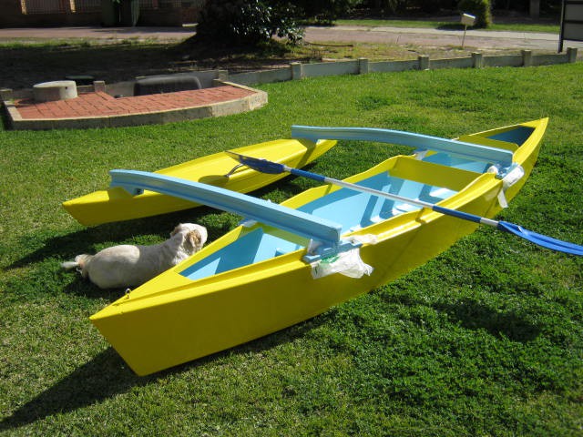
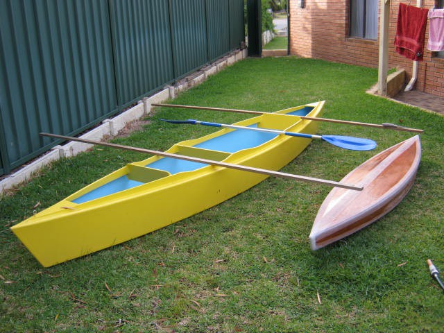
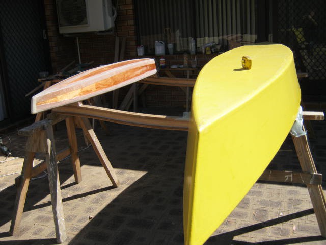
Here is the latest picture of my canoe:
![]()
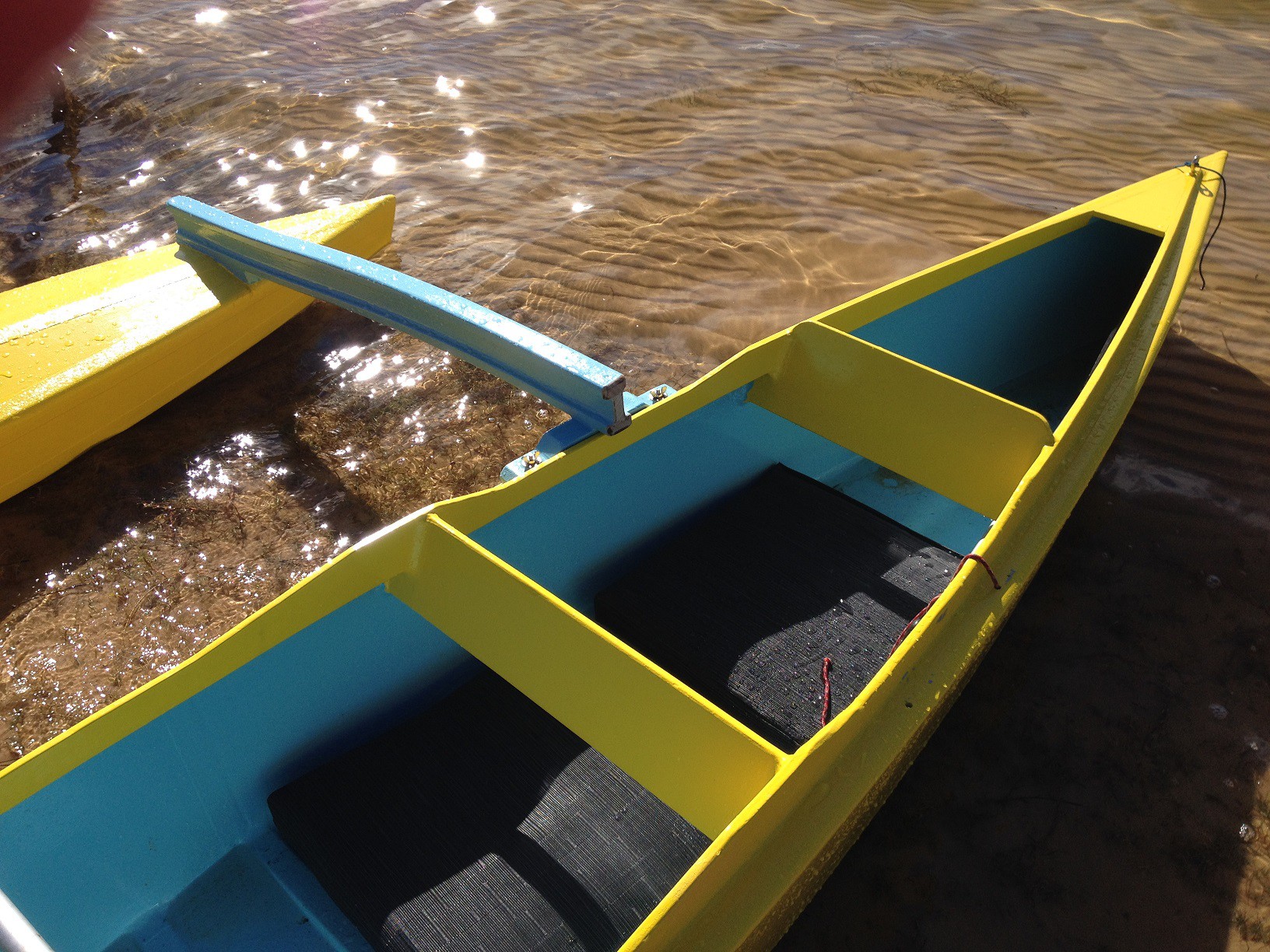
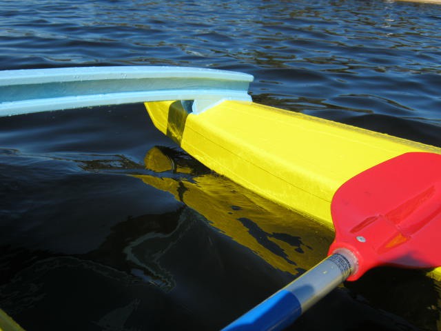
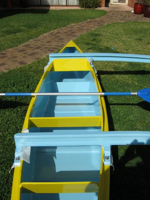
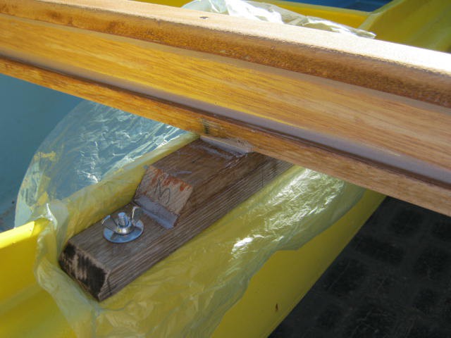
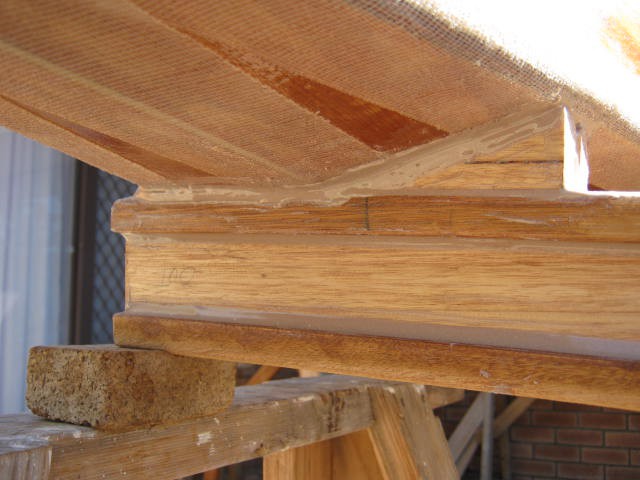
Here is a closeup of the cutoff rear cross-beam:
![]()
Weathercocking
The canoe weathercocks quite badly when paddling into the the wind (what little there was!). four strokes to one. Downwind it tracks quite well. I need to fix this. One option is a small skeg to increase the tracking (at the expense of maneuverability). A trimming rudder is another option but best to keep it simple if I can.
Splash Canopy
Another must is a splash canopy (I think it is called a spray cover or spray deck). Not very cool to get in dry and get out soaked because of drips from the paddles. I am thinking of a tilt up frame that would look like this (crowned at the rear):
![]()
(source:http://www.newfound.com/images/eclipsehalfskirt.jpg)
Buoyancy Tanks
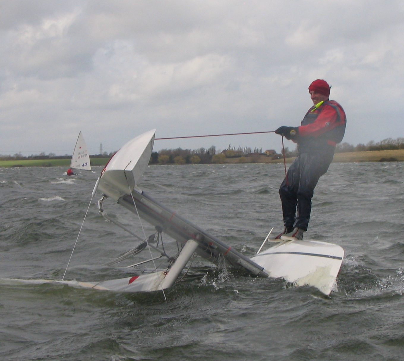
I need to consider buoyancy tanks. In the event of a capsize (really?), I can up right the canoe by tying a rope the pontoon (handle), standing on the upside down canoe hull and pulling it over:
![]() He says "Give it a try - it is easier than you would think."
He says "Give it a try - it is easier than you would think."(source: https://www.thebeachcats.com/forums/viewtopic/topic/12778).
Fourth Paddle
Had a fourth paddle and managed 5 km/hr but really I need focus on paddle technique and increasing my back flexibility (I am lucky to touch my knees!).
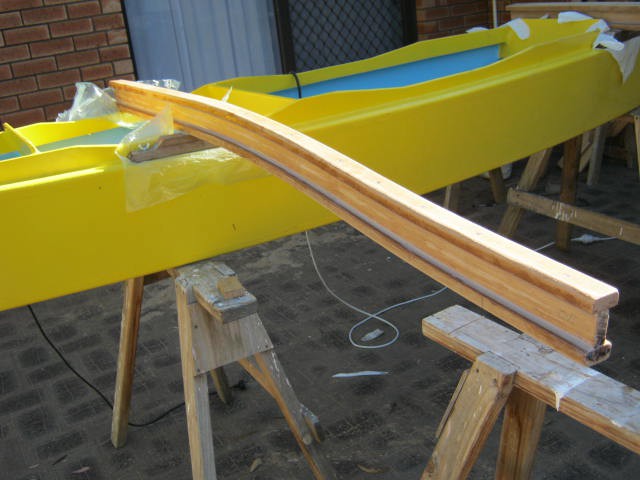
Skeg
My partner is using my car for a few days so I am stuck at home. So I added a skeg to to the canoe. No science to this, just approximately what I have seen before:
![]()
I used a hot air gun to strip the paint before fixing the skeg. The primer is really tough to get off so I did not try too hard (its not going to debond easily). I have fixed the wood with mould preventer and will use some fiber-glass tape toughen it up for scrapes before repainting.
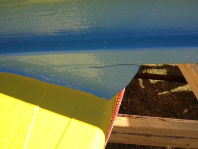
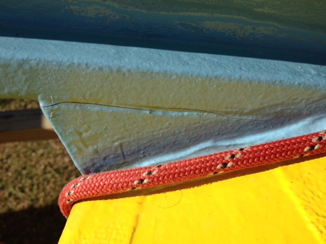
Cross Beam Failure
Failed in torsion (probably failed during transport while on the trailer):
![]()
And:
![]()
I should have fibre-glassed the joint when I had the chance. This will take time to fix as I have to detach all the joints, sand the surfaces back to wood and start again. But after I work out what to do.
Regards AlanX -
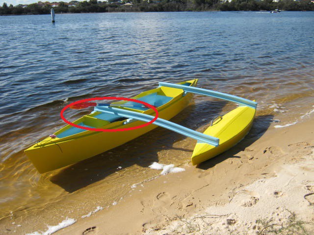
Modification for a Dead-Weight (Grandson)
06/06/2017 at 11:50 • 0 commentsSecond Test Paddle
Took the grandson for a test paddle. The best place to put him was behind the main seat (circled):
![]()
The problem is that the cross-beam is in the way. Although he can wiggle in, it is not safe if the out-rigger capsizes as it will be hard for him to get out. I can move the seat back by cutting it out and gluing in a new one, or I can cut off the cross-beam, to make it safe (i.e. he will fall out if it capsizes)?
The Australian Standards (AS 4132.1 4.8(b)) says the cross-beam structure needs a moment capacity of M = 3*Disp*Bh where:
- M = required moment capacity (kNm)
- Disp = weight of boat with payload (t)
- Bh = distance between hull centre lines (m).
- The displacement is 165 kg (= 35 kg + 90 kg + 40 kg ) or 0.165 tonnes.
- The distance between centre lines of the hulls is 1.25 m.
The required moment capacity is therefore 0.619 kNm. This is somewhat less than I expected!
The working stress for Tasmanian Oak is 35 MPa so the required section modulus for the uncut beam is 18e-6 m^3. The designed section modulus is 58e-6 m^3. So easy, cut out the rear cross-beam to make room.
AlanX
-
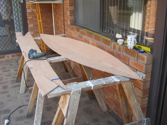
Test Paddle
05/25/2017 at 06:17 • 0 commentsTest Paddle
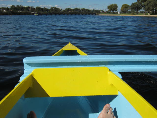
I have been waiting a week or so for some nice weather. Today is light winds and 22 degrees C. The last time I paddled a canoe was about 10 years ago. I certainly have not developed a "stroke" so this was quite new for me. Anyway, I spent half an hour on the water and I am quite happy with the outrigger. It does not seem to pull in any direction. The forward cross-beam and the pontoon are well clear of the paddle. I do clip the rear cross-beam so the stroke need to be ended sharply or deliberately. An extra 50 mm would have been good. Here is the in the water photo:
![]()
I found a good launch site a short walk from the road on the Canning River (off the Swan River).
Here is a forward view:
![]()
The cross-beam is wet from paddle drips. The foot rest feels okay. Here is the pontoon:
![]()
For paddling around in calm water the whole canoe/outrigger is grossly over designed. If building another I would certainly scale back the cross-beams size and the pontoon skin thickness.
Project Completed
As it stands the project is completed. I have certainly solved some construction issues (i.e. how to stitch and glue a seaIed pontoon).
I may add buoyancy tanks to the main canoe, and I may add a sail/centreboard/rudder. But that is another project.
AlanX
-
Trailer
05/13/2017 at 01:39 • 0 commentsTrailer
At about 35 kg the outrigger canoe is too heavy and awkward to lift above my head and place on my car roof-rack by myself. So no choice but to use a trailer. Here is my old trailer:
![]()
Here is the new trailer:
![]()
The lower longitudinal is attached to the pipes of the trailer with U-bolts. Then a set of transverse beams and then a a set of 3 m longitudinal beams. I use 130 mm long (recessed) coat-bolts to join the timbers. The timber is 90 mm x 37 mm H3 treated F7 pine. F7 is rated at 6.9 MPa in bending. How strong is that? Not great! The rear overhanging beams (~0.85 m) are rated (i.e. working load) at 42 kg each (84 kg total). For short duration loads you can double this (168 kg). To break it approximately 284 kg would be required.
Even though it is H3 treated it will still need to protected against sunlight. So it will need to be sealed and painted for longevity (and to retain the design strength).
Busy with social engagements this week end so if the weather is good on Monday then I can test the out-rigger in the water.
Weight
Looking a the weight of other light weight kayaks (~15 kg) I concluded that my weight estimate of 35 kg is quite reasonable. However, I could certainly get the weight down by using 4 mm plywood rather than the 6 mm plywood for both the canoe and the pontoon. The cross-beams could also be reduced in weight as well. I think 25 kg could be achievable without extreme measures.
AlanX
-
Painting
05/09/2017 at 07:11 • 0 commentsPainting
Painting takes time. Paint one side, wait a day, paint the other side, wait a day, repeat.
Two coats of primer and two to three coats of paint.
I have finally worked out how to use primer! Paint the imperfections with primer and sand flush, repeat until surface is perfectly flat, then paint.
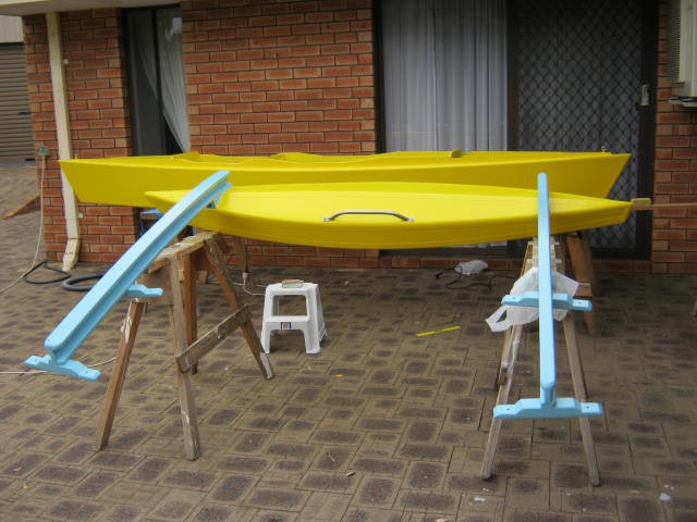
Here is the outside painted:
![]()
Just the inside of the canoe and the final coat of the cross-beams to go.
You may note that the colours are not quite the same. The paint I used 10 years ago is no longer available.
You can also see that I added a handle for the pontoon. It makes it easier the lift as cross-beams are too far apart leaving no easy way to lift by myself.
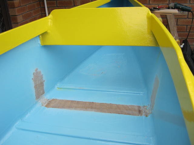
I decided to add a foot rest to the canoe. It should save pressure on my knees from clamping the sides of the canoe. Here I used the heat gun and a scraper to get back to wood:
![]()
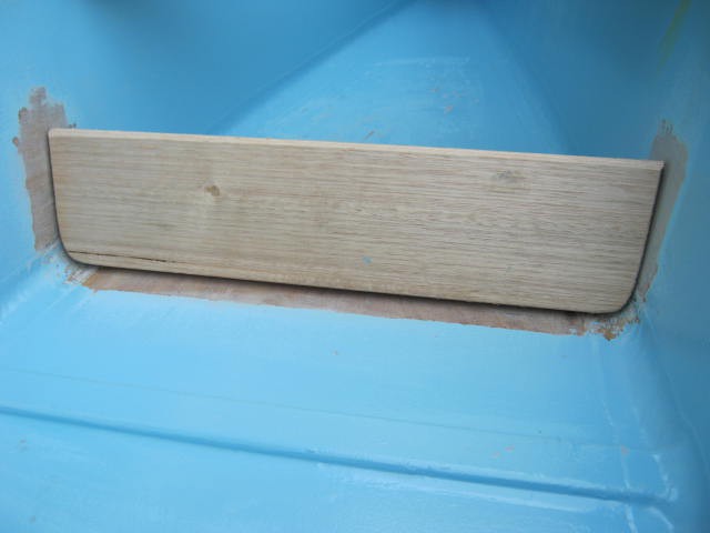
Next, I fitted the foot rest:
![]()
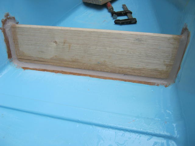
Finally it was epoxied in:
![]()
So all it needs is few coats of primer and a few coats of paint.
There are some water splashed in the canoe as a wet finger is used to smooth the final epoxy fillet seam.
The yellow (hull) paint needs a few days to harden so I should be in the water by the weekend.
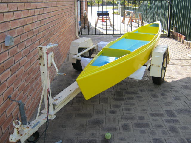
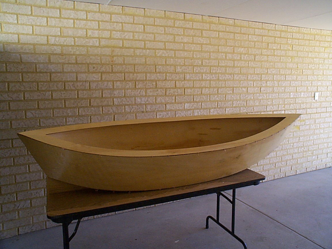
Painted
Well the painting done, here it is assembled (plastic on the bolt joints as the paint has not hardened fully):
![]()
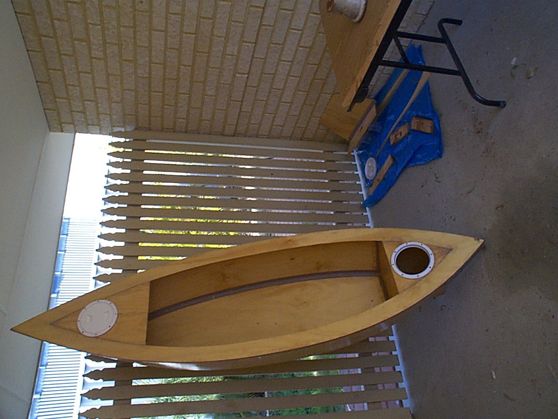
Here is the inside:
![]()
The main problems are the size and weight. Standing in between the hulls and lifting it feels about 30 kg to 40 kg. A quick calculation suggests:
- plywood 20 kg
- cross-beams 7 kg
- epoxy and filler 5 kg
- paint 2 kg
- Total +34 kg
In general I have built a bit too heavy duty.
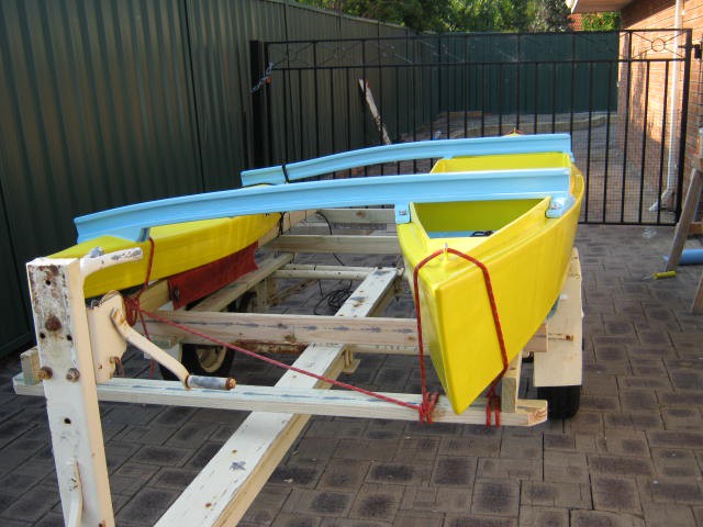
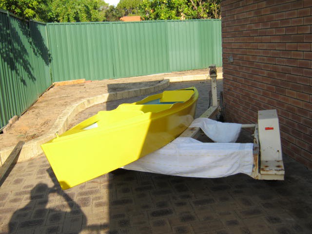
So it will not car top (at least on my car) and in any case I probably cannot lift it above my head (without risking an accident with my car or hurting myself). It will need a trailer. I have a small boat trailer but I will have to make up a cradle and fix the lights:
![]()
And from the back:
![]()
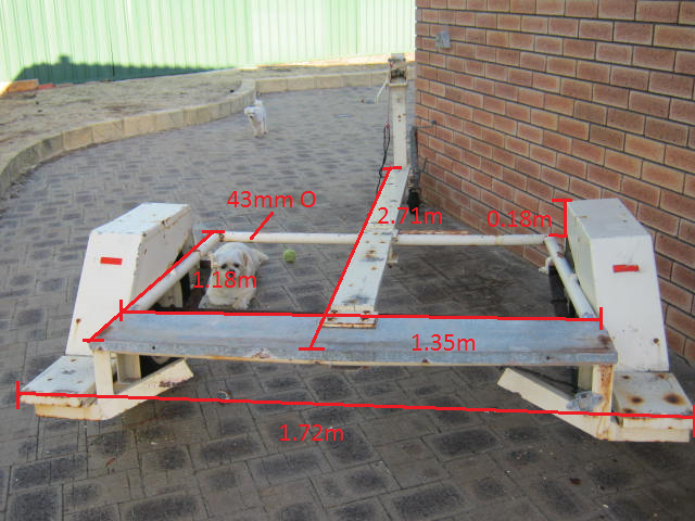
The trailer looks like it would make a good two canoe unit. Here are the dimensions:
![]()
After Thoughts
It was a mistake gluing the cross-beams to the pontoon, I should have used bolts when I had access to the inside of the pontoon.
Buoyancy Tanks
I have a thoughts of buoyancy tanks front and rear for the canoe. I would then be practically unsinkable. But I should try it out first.
Sail
I have a suitable sail but will need a rudder and centre board. But worth considering later.
AlanX
-
Cross-Beam Design
04/14/2017 at 09:26 • 0 commentsThe Pontoon Bridge/Spar(s)
I have been playing with various options. The torsion maths says a single 6 mm plywood box (bridge) about 150 mm x 150 mm square will work (also 180 mm x 100 mm). The plywood can also be designed to take a curve. Otherwise a single 90 mm x 90 mm solid wood spar. Attaching the bridge/spar to the pontoon is straight forward. Attaching to the canoe is problematic. I am considering a wooden knee(s) (i.e. angle bracket) between the canoe outside and the bridge/spar.
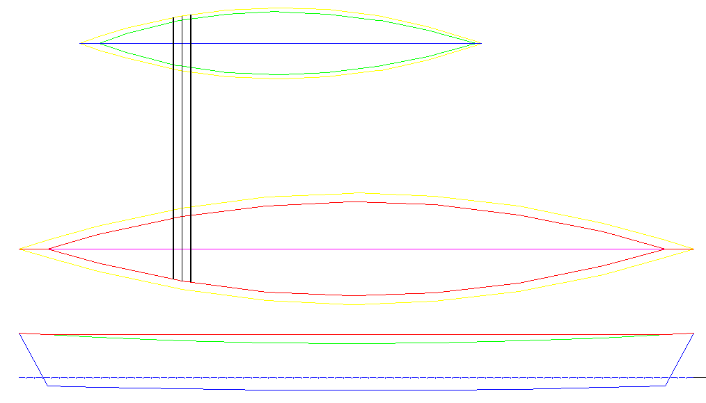
At the moment the bridge/spare is forward of the paddler (on the right) but I think it would be more out of the way on the left. The pontoon has to be clear of the paddle stroke which I calculate as about 1 m from the canoe sheer and 1.5m forward of the paddler:
![]()
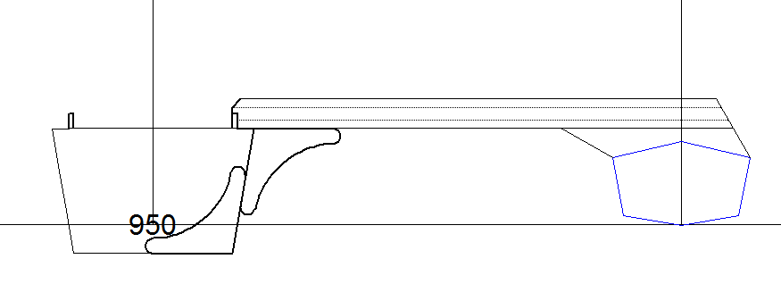
The knee(s) will require longitudinal reinforcement on the canoe inside/outside (perhaps another set of knees):
![]()
I will have to look at the option for the bridge/spar behind the paddler, and the lighter twin spar options as well.
Plywood Bridge
I had trouble finding suitable timber for the spars and knees. The plywood box is relative easy to make and would be attached with fibreglass tape. The box section is 180 mm wide and 100 mm deep with a minimum thickness of 6 mm. Likely I will use 18 mm thick pine for the side faces and 6mm plywood for the top and bottom:
![]()
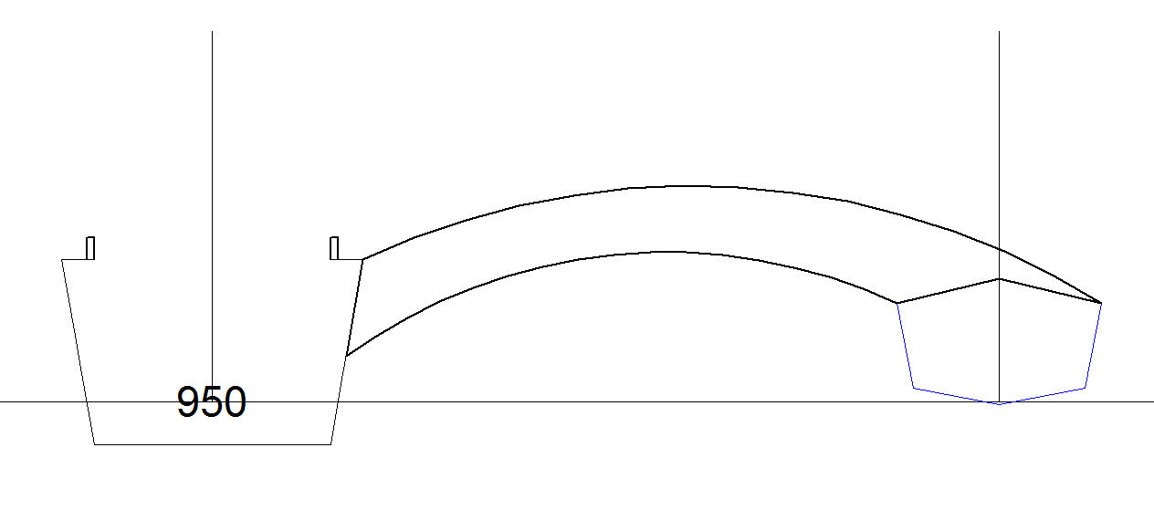
I am still having design problems with the plywood bridge. The main problem is the stress levels on the canoe hull (circled red below) are far too high:
![]()
Basically the bridge is like a can opener on the side of the canoe hull. I think I will have to go over the top like I did for the pontoon.
![]()
Basically I need to get the stresses directly to the outer skin.
I was a bit worried that I was over-designing the bridge so I checked out (reverse engineered) some designs on the Internet. The keyword here is "cross-beam" rather than bridge or spar. There are a number of designs (for bigger boats) that match my loading estimates after scaling.
I have been trying to rationalise why most of the design on the Internet don't have the stress problems that I have. I did notice that some designs did have pretty heavy duty saddles for the cross-beams. Eventually I noticed that the wale and skin thickness for most of the designs are pretty heavy duty! More than enough to just boat or lash on (with a cross-member and bulkhead backup).
I have gone back to a hardwood cross-beam with a saddle for distributing the load:
![]()
I have been going around in circles with the cross-beam design. The problem is that I am trying to avoid the need to sanding the interior paint back to wood for epoxy joins. My fingers will not like me if I go down this path. Still the best option is to install a bulkhead or two to bolt the cross-beam to.
Checking the Internet the method of choice seams to be a heat gun and a scraper. I am not going back to chemical strippers (the modern stuff is pretty useless and the stuff is just as awful). Not keen to use screwed in frames/brackets. The heat gun may also work with removal of the copper tie wires. For A$65 worth a try. I have a bathroom ceiling that needs stripping anyway (I stripped it with paint stripper a few years ago and never again).
Here is the next proposal:
![]()
I have reduced the cross-beam to 100 mm x 64 mm using four 64 mm x 18 mm hardwood DAR. I have added two 12 mm plywood bulkheads to attach the cross-beam to the canoe. They are only 75% of the required design strength so rather than increase the thickness I will sheath them in fibre-glass.
I have looked at some designs on the Internet and the bulkhead seems to be the preferred method although I did see two half frames (similar to my orignal knee design).
The bulkhead options allows me to add a buoyancy tank (or two).
Before painting I have to attach the cross-beam and I am still struggling to determine the easiest way of doing this. I had a look at some timber at the hardware store yesterday. Not cheap! The simplest solution is a 90 mm x 90 mm solid pine but it really looks heavy compared to the pontoon!
The nominal load is 100 kg on the middle of the pontoon as the pontoon displaces 97 kg. I should have designed a thinner pontoon with less buoyancy! This results in bending moments and torsion. The minimum size solid wooden beam is 90 mm x 90 mm, the limiting factor is torsion (shear stress). If I use twin cross-beams (of solid wood) then the beams can be smaller (55 mm x 55 mm) and the torsion issue disappears. The Michael Storer Design looks good:
![]() (source: http://www.storerboatplans.com/Canoebits/canoeoutriggers.html)
(source: http://www.storerboatplans.com/Canoebits/canoeoutriggers.html)I while back I did design a "banana" pontoon as above:
![]() But I prefer this one:
But I prefer this one:![]()
Something else I could have done was design the pylon for the cross-beam in the hull design.
Anyway, here is an I-beam for a twin cross beam:
![]()
The flanges (the outside edges) are 42 mm x 19 mm hardwood DAR and the web (the inside) is cut out of a 90 mm x 19 mm hardwood DAR (1.8 m long). The flanges will need to soaked in boiling water to take the curve. The cross-beams will sit on a saddle on the canoe (not shown).
Updated Twin "I" Cross-Beam
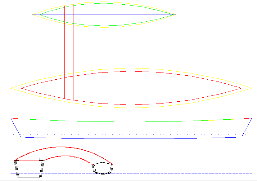
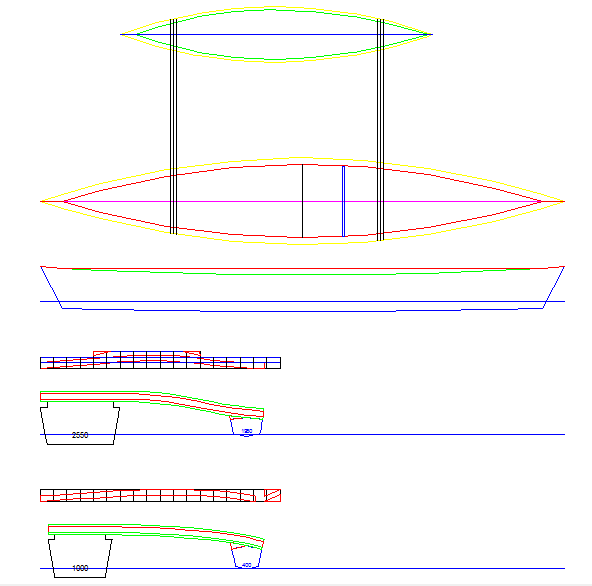
Here is a design with the new cross-beam locations considered:
![]()
Looks pretty doable.
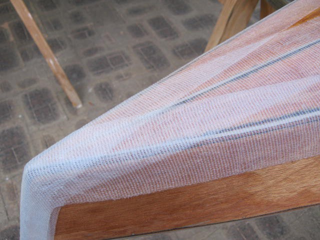
Taping the Seams
This time I used Dynel Tape instead of fiber-glass tape. One good thing about fiber-glass tape is that it almost invisible when epoxied, no so with Dynel:
![]()
Al close up:
![]()
It is also thicker. But no problem it will be painted anyway.
The epoxy mix includes wood preservative this time around and I have coated the plywood.
Next is to trim the tape at the ends and then tape the top of the pontoon.
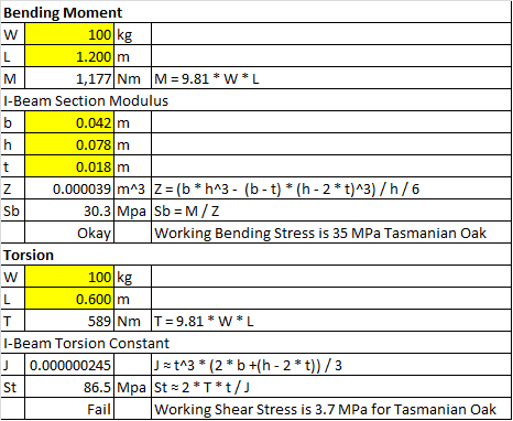
I-Beam Calculations
Here are the I-Beam calculations:
![]()
A single cross-beam is strong enough in bending but fails in torsion. We can solve this by (1) adding a second cross-beam to remove the torsion or (2) increasing the size of the beam to meet the torsion stress limits. The cross-beam is just too big for case (2).
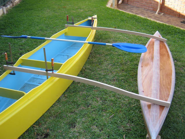
Mock-up
Here is a muck up of the out-rigger. After trying it out (lawn paddling?) I moved the cross-beams aft 250 mm. The 1.2 m centre-line offset was okay but I bumped out an extra 50 mm.
![]()
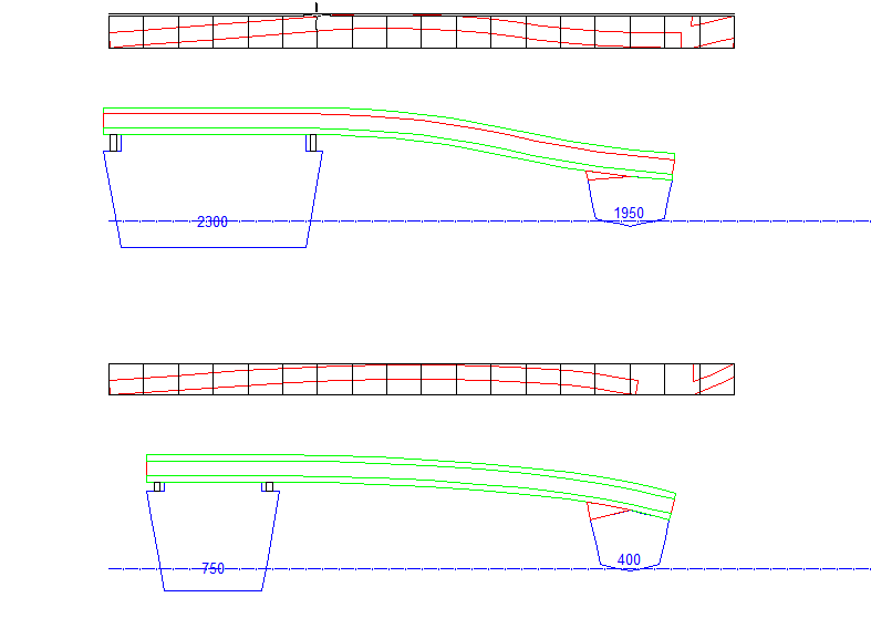
Updated the design:
![]()
I am going to either use 90 mm wide DAR (bottom) or laminate 42 mm x 19 mm DAR to the width I need (top):
![]()
Finally I exported the shapes to excel for lofting.
I will epoxy glue the beams to the pontoon but also use fibre-glass to reinforce (i.e. spread the load of) the join.
Cross-Beam Webs Cut Out
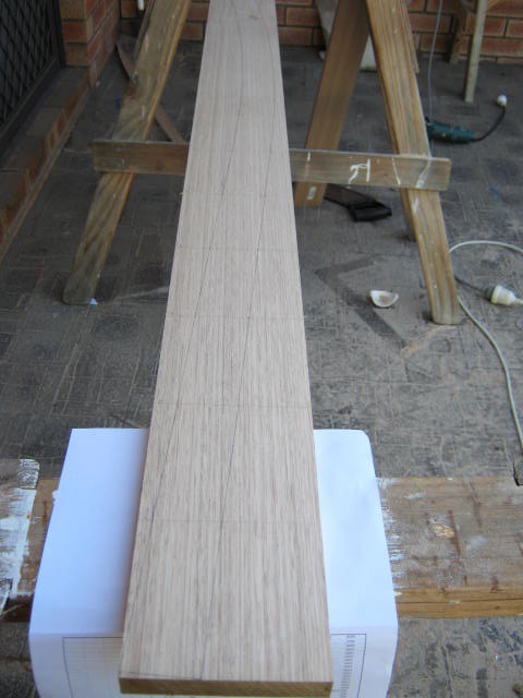
Cut out the webs of the two cross-beams. Here is the lofting of the forward beam:
![]()
Another hardware store had both 90 mm and 110 mm wide planks so no need to laminate a wider plank. Mock fitted them to the canoe:
![]()
Checked the sideways cross-beam strength and decided to use 65 mm wide flanges (rather than 42 mm).
The bending radius for the forward cross-beam is about 2.5 m and the rear cross-beam is about 3.0 m. Very unlikely I can bend Tasmanian Oak along the grain that much (e.g. 19 mm plywood along the face has a bending radius of 6.7 m) without steaming or laminating thinner strips (i.e. 9 mm). I will have to see what I can find.
Steam Bending
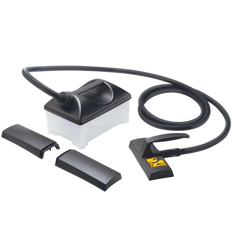
That was not hard, a wallpaper steamer (A$100):
![]()
Add 4 litres of water (80 minutes of steam), plug it in (2000W) and let her rip. Just need a simple steam box. I think I only need something that can take two 65 mm x 19 mm DAR and steam a length of up to 1.2 m. A length of 100 mm diameter PVC pipe?
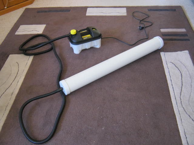
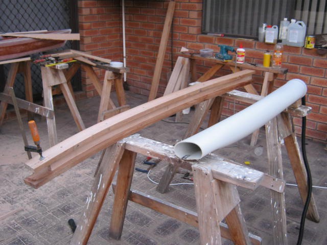
Well here it is, a 1 m length of 100 mm heavy duty PVC pipe, two end caps and the wallpaper steamer (about A$115 all up):
![]()
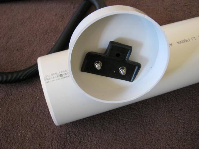
I cut down one of the steam "cups" provided and bolted it inside one of the end cap:
![]()
I also drilled two small holes at each end to let the water out (and to stop the end caps from being blown off. I can replace the 1 m tube with a longer one at anytime. About the only other thing that could be done is to add wooden dowels across the tube to suspend the wood. A 1 m tube will work as I only have to bend one half of the wood for the cross-beam.
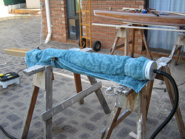
Here is the steamer in action:
![]()
And here is the first cross-beam (note how the tube has basically lost its shape):
![]()
PVC tube is pretty hopeless in this application. I will have to build a wooden box.
The steamer however worked fine. With hot water it took about 5 minutes to start boiling and the steam box took another 5 minutes to blow a full head of steam.
The idea of clamp, check/adjust, drill and screw is just too slow. It took 15 minutes and by then the wood had cooled. Still I only need to epoxy glue the web to the flanges and the cross beam is done. The beam itself is has a pretty solid feel.
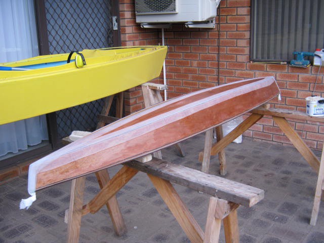
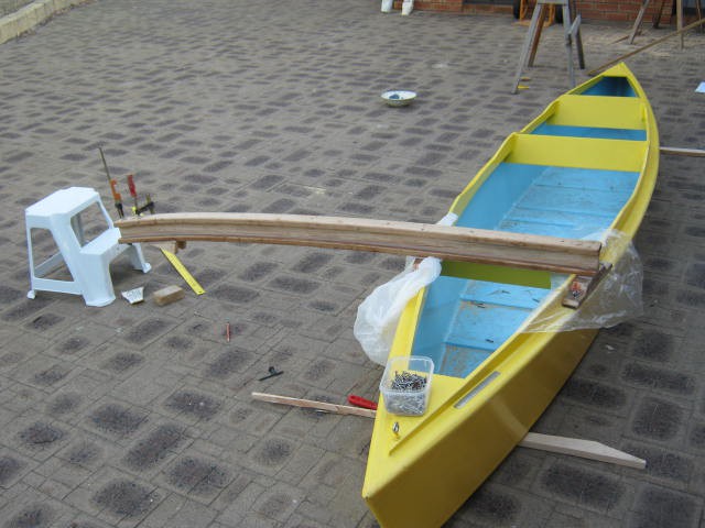
First Beam Done
Well done excluding finishing. Here it is:
![]()
The plastic is to stop the epoxy gluing the beam to the canoe. The saddle is glued and screwed to the beam and bolted to the canoe deck/chine. Here is another view:
![]()
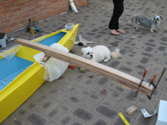
Here is the rear cross-beam:
![]()
You may be wondering how the cross-beam is connected to the saddle? It is glued:
![]()
Now it sure looks like a weak spot! The limiting factor is the strength of the wood in tension perpendicular to the grain (not the glue). This is not usually specified for wood because that say "don't do it!". Anyway I have done it so is it strong enough? An estimate for the tensile strength perpendicular to the grain is 1/10 to 1/20 of the tension parallel to the grain. So I will use 1/15 as an estimate. Here are my calculations:
Glued Cross-Beam Strength Estimate Value Units Comment Parallel 60 MPa Ultimate Tensile Strength Estimate Perpendicular 4.0 MPa Approx. 1/15 Width 0.042 m Breath 0.042 m Area 0.00176 m^2 Ultimate Load 7056 N Spacing (gunwale to gunwale) 0.5 m Lever Arm (gunwale to pontoon centre) 1.0 m Maximum Load (at pontoon) 3528 N Safety Factor 3 Very uncertain strength parameter Working Load (at pontoon) 1176 N Working Load (at pontoon) 120 kg Okay! So it seems to be strong enough. Maybe I will add some fibre-glass tape for insurance.
Attaching the Pontoon
I turned the canoe upside down so that gravity would settle the pontoon onto the cross-beams with minimal stress (i.e. twist):
![]()
A view of one of the glue joins:
![]()
The area of the glue join is five times the saddle so no need for any strength calculations.
---
If I was doing this again I would have installed two long bolts sticking out of the pontoon. That way I could just bolt the cross-beam to the pontoon.
---
Some remedial epoxy work, a good sanding, a coat of epoxy/preservative and a paint job remains.
AlanX
-
Lofting, Cutting Out and Gluing Together
04/02/2017 at 06:34 • 0 commentsLofting
Bought some marine plywood yesterday. I could not get 4 mm so the skin thickness is now 6 mm. Formatted the lofting offsets in Excel and printed them out:
![]()
Along with a plan:
![]()
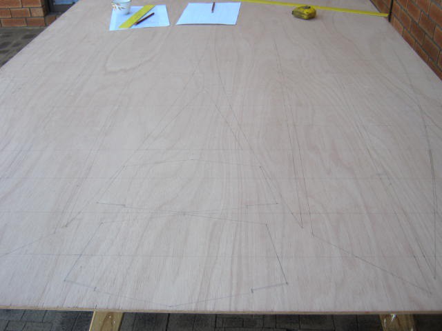
After 2 hours (half done), time for a coffee break:
![]()
I will say it was worth redigitising the layout design to align with the 100 mm offsets or sections.
Lofting Done
Complete the lofting in 200 minutes excluding the coffee break. That is about two offsets per minute. A useful statistic for next time.
If I had a suitable CNC machine (I can dream!) then I would have designed the wiring holes and perhaps a toothed edge for seam alignment.
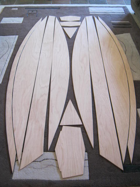
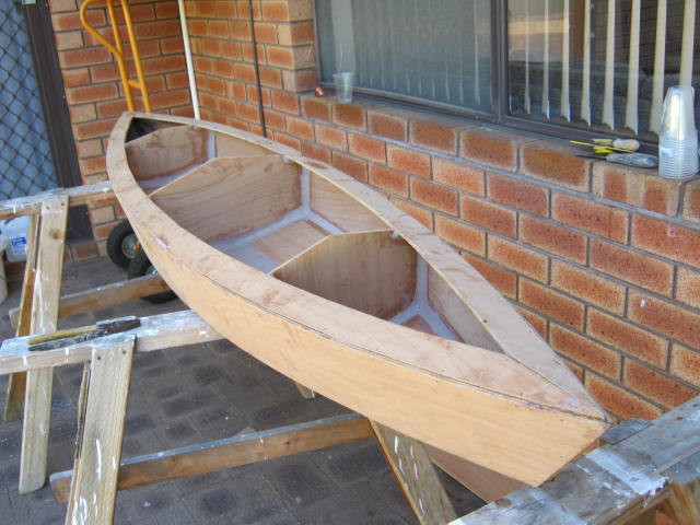
Cutout, Trimmed and Sanded
Took about 3 hours to cutout, trim and sand the panels.
![]()
For the amount of work spent on the pontoon I could have built a full size kayak!
Assembly
The next task is to drill the wiring holes. I should get away with 150 mm hole spacing. I can always infill if necessary.
I will assemble and glue the "harpins" (i.e. the two outer thin crescent shaped pieces and the two triangles) first, then the deck using the harpins and bulkheads as temporary forms to get the right shape. After that the harpins are used with the bulkheads for the main hull. Finally the deck and hull as glued and screwed together.
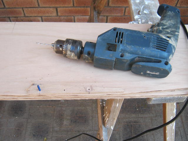
Stitching the Hull
Made up a template that drills 100 mm spaced holes 7.5 mm from the edge. I start in the middle of the panel and work my way to the ends. The blue pin in the image below pops into the last hole drilled to keep everything properly aligned:
![]()
I taped the panel in pairs to reduce the drilling effort:
![]()
Here is the bottom and side panels wired up:
![]()
Copper wire works best as it can be heated with a propane torch to allow removal (this trick does not work with steel wire). Unfortunately the copper wire is a bit light duty so I need to be gentle when tightening the wire to close the gaps.
All done (about five hours later):
![]()
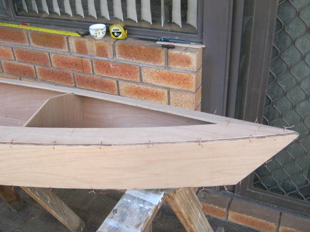
A close up of the front:
The wires need to be tightened before being epoxied. I am only going to put dynel tape on the outside, so the bulkheads will be epoxied at the same time as the seams.![]()
The Deck
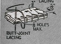
I could join the deck with copper wires as well but I want to try nylon lacing instead:
![]()
(Source: "Graefin 10" by Will Graef (Science and Mechanics Magazine, May 1964))
The nylon lace is stretchy so the join and be opened. More holes to drill and fill but less issues with heating the copper wire to get it out. Also easier on the fingers (the copper wire ends are sharp). I suspect getting the string tension just right will be important.
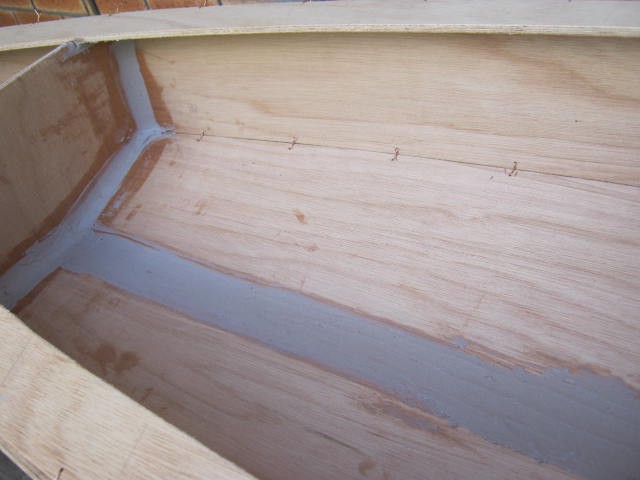
More Seams Done
I made up two batches yesterday and most of the inside of the hull is done. About 90 minutes to mix and place. The main problem is that the pontoon is just a little too small to easily place and smooth/finish the filler and I can't get my head in to see what I am doing. The filler is very sticky and hard to place/finish, you need room to work. Still two more batches should finish the inside seams. Here a examples of the work:
![]()
Finished the inside seams. Tomorrow I will try the heat gun on the copper wires to see if they will come out. After that a slightly more runny mix of epoxy filler to fill the outside seams and the wire holes.
![]()
Epoxy Safety
I don't use polyester resin as it is not safe without the proper breathing gear. Epoxy is pretty safe but you can become hyper-sensitive to it (i.e. that would mean the end of my boat-building) so I now use rubber gloves. I once used acetone to clean-up but now I use white vinegar. It deactivates the epoxy allowing it to be washed off with detergent. It is not perfect as it still leaves a residue but good enough. I don't try to reuse bushes etc. I reuse metal spatula/scrapers by grind off the epoxy after it has hardened. The filler is a hazard to your lungs so I would recommend a face mask when mixing it with epoxy (or at least hold your breath not to breath the dust!). I have swore off fibre-glass tape because sanding the (sharp) edges a pain (lots of sharp fibrous dust). I will be trying dynel tape (a form of very tough nylon). It is more expensive! It is about 40% of the strength of fibre-glass tape so good enough taping seams on canoes and dinghies.
Hot Air Gun
Previously I use a propane torch but this time I will try a hot air gun. The hot air gun works very well. 10 seconds on each end of the wire is usually enough. Repeat for difficult wires. Here is the pontoon de-wired:
![]()
It's a warm day (~28 degrees C) so the epoxy is going off in about 1/2 an hours so quite a bit of wastage. Here is the bottom seams and wire holes filled:
![]()
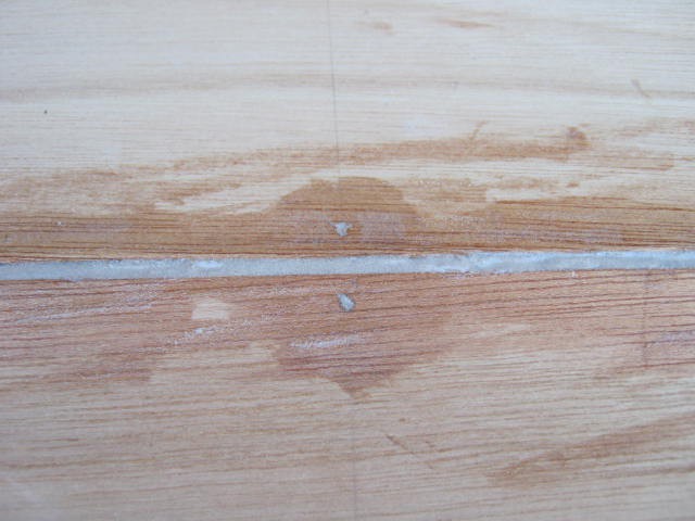
A close up:
![]()
The only problem was the occasional break in the fillet on the butt join when I pulled out the wires:
![]()
I will just fill these when it is convenient.
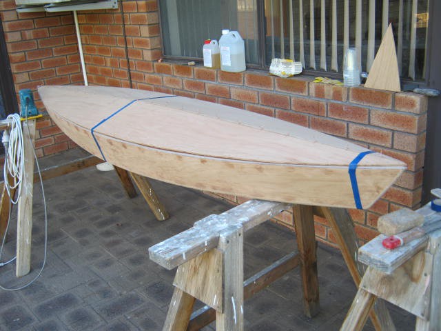
Lid
I wired up and taped the lid to the hull:
![]()
And then "tacked" the top seam:
![]()
After the tack had set, I removed the wires and finished the top seam:
And the bottom seam:![]()
![]()
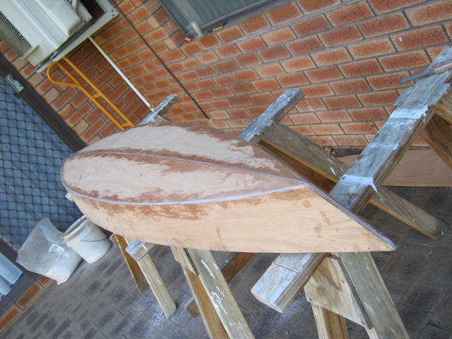
Pontoon Sealed
Sealed the pontoon:
![]()
A final sanding and then it needs to be taped. I will use some penetrative/preservative in the epoxy this time. After than it needs to be painted.
AlanX
-
DeltaCad Macro Completed
03/31/2017 at 13:05 • 0 commentsDeltaCad Macro Completed
All I can say it was a bit of a marathon getting the code working reliably. The issue is that the underlying processes (wire-framing) is not unique/deterministic. Asking the macro to sort out lazy chine offsets was a dead end.
Why migrate from the spreadsheet version previously presented? After all it works! The reason is that even simple designs take forever to code and it is just too hard for more complex projects. The new DeltaCad macro version handles simple hulls easily and the more complex designs are slow but doable.
Design Process
The process consists of two macros/files:
- BoatOffsetTable.xlsm
- BoatOffsetTable.bas
The Excel file and macro allow you to enter the offset table and then to export the design to a CSV file for DeltaCad.
The DeltaCad macro imports the CSV, draws the design and unfolds (develops) the hull.
Note: DeltaCad can be purchased for US$40 from https://www.deltacad.com.
Workflow
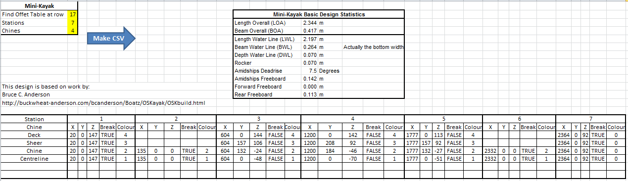
DeltaCad does not have a suitable table entry process which is why Excel is used. Below is the Excel offset table for the “Mini-Kayak”.
![]()
“Mini-Kayak” is an adaptation of work by Bruce C. Anderson (http://buckwheat-anderson.com/bcanderson/Boatz/OSKayak/OSKbuild.html). The actual design is too small to be of practical use as a Kayak (refer to Anderson’s webpage).
The above offset table has three additional features over an offset table:
- Chines have a colour for easy identification.
- Chines can be invisible (and ignored) if the colour is “0”.
- Chines can have a “break” or a sharp bend.
Notes:
- The design is in millimetres.
- The stations are rounded to the nearest millimetre.
- Any duplicate stations are deleted.
- Stations within 5 mm of each other will have “breaks” automatically added.
- Colour 0 is not processed.
- If an interpolated value appears wrong or wildly off then you will need to add “breaks” to the chine stations near the problem area.
- No curvature checks are made, the design may not be developable (i.e. the plywood may break).
The offset table is exported to DeltaCad as a CSV file. The name of the CSV file is the same as the Excel WorkSheet name. To execute the macro just click the blue “Make CSV” arrow as shown above.
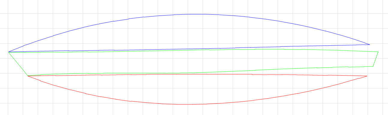
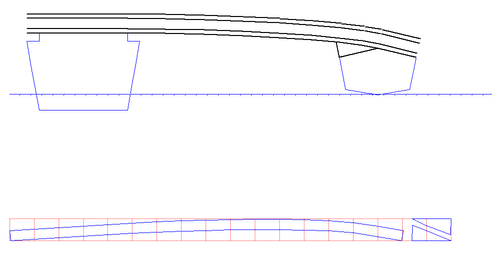
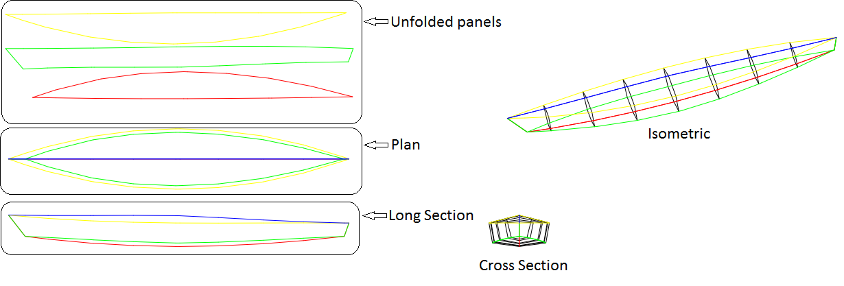
In DeltaCad the macro (“BoatOffsetTable.bas”) is run to import the CSV file and draw the design. For complex designs, the actual process is iterative (i.e. chine by chine). Below is the imported and unfolded “Mini-Kayak” showing the main drawing components.
![]()
Note: The unfolded panels are the cut-outs for the design and only one side is shown.
Macro Options
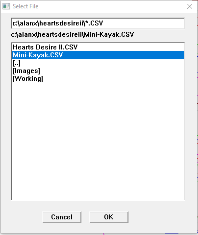
When you run the DeltaCad macro, it first presents a file manager window. It starts in the DeltaCad macro directory. You will need to navigate to your working directory (i.e. where the Excel file is located) and select and okay the CSV file. For the “Mini-Kayak” it is called “Mini-Kayak.CSV”, as shown below.
![]()
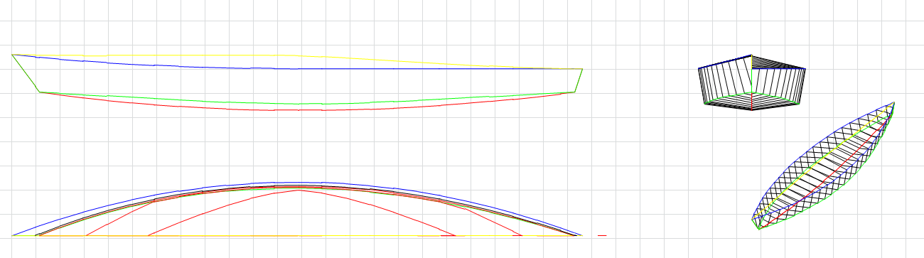
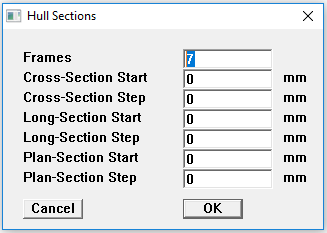
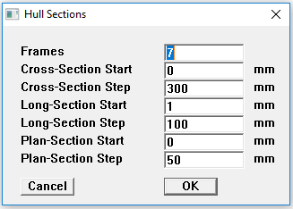
The macro then presents the “Hull Sections” options box. Set the number of frames to 7 and zero the remaining entries as shown below. This option adds additional frames to the hull model.
![]()
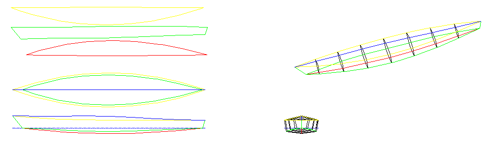
You should see the following design.
![]()
Other Options
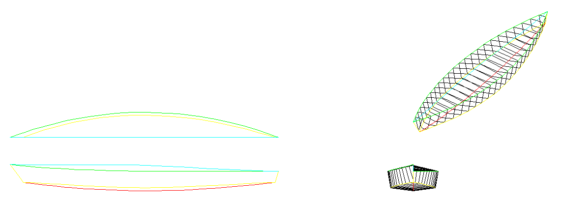
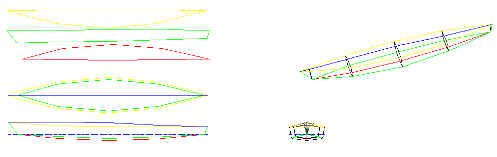
If the “Frames” entry is set to zero then the offset table as entered in Excel will be drawn as below.
![]()
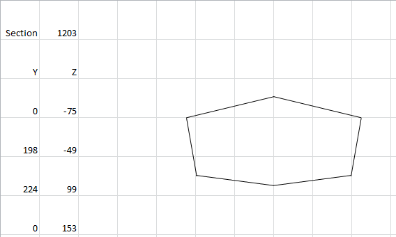
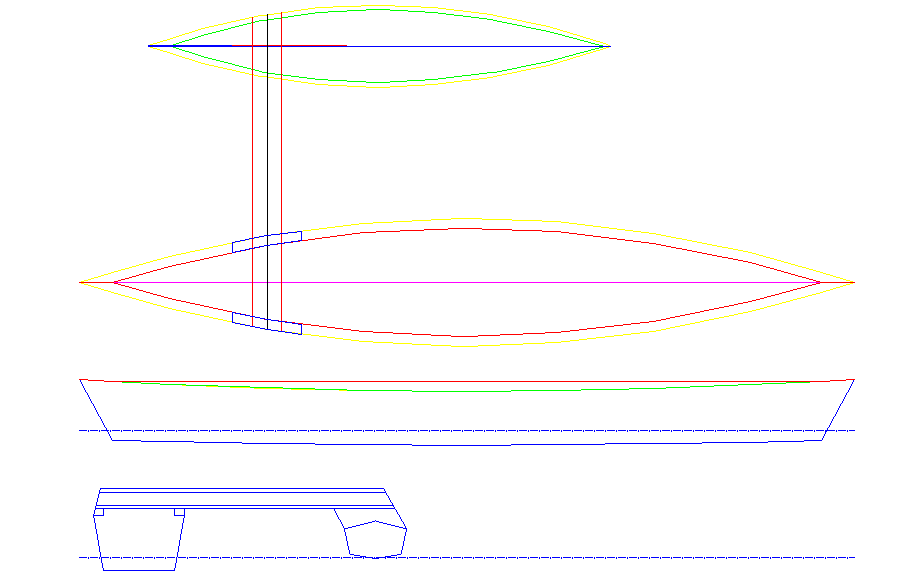
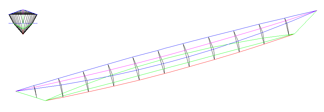
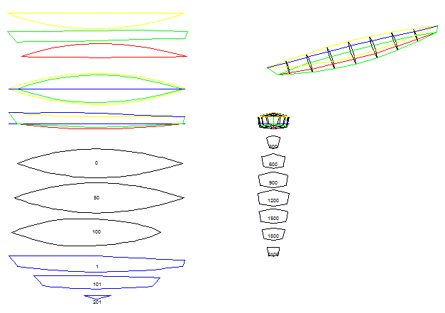
The other option entries, create different sections (cross, long and plan) through the model. For example the following options, shown below, also draw a series of cross-sections, long sections and plan slices.
![]()
![]()
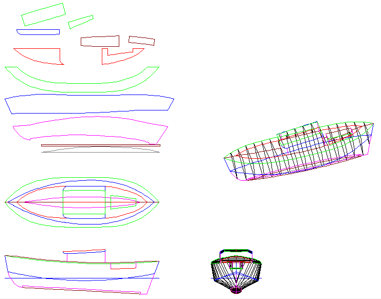
More Complex Designs
The program is capable of more complex designs but the offset table entry process is rather time consuming. Shown below is “Heart’s Desire II” a design by William Atkin.
![]()
Back to the Pontoon Design
Okay, I have generated the pontoon design file in DeltaCad, what next? No big deal, digitise "shapes" over the pieces I want (delete the all the segments when done) and lay them out. Only took about 30 minutes. Below is the cutout design on a single sheet of 4 mm marine plywood:
![]()
What is now remaining is to generate (i.e. write a macro to generate) a set of text offsets for marking out the shapes on the plywood (the black box in the image above).
The Pontoon Bridge/Spars
Not a big deal here. Just have to decide what I want it to look like before designing it.
Files
I have uploaded the two files. If you have DeltaCad then have a play.
Update
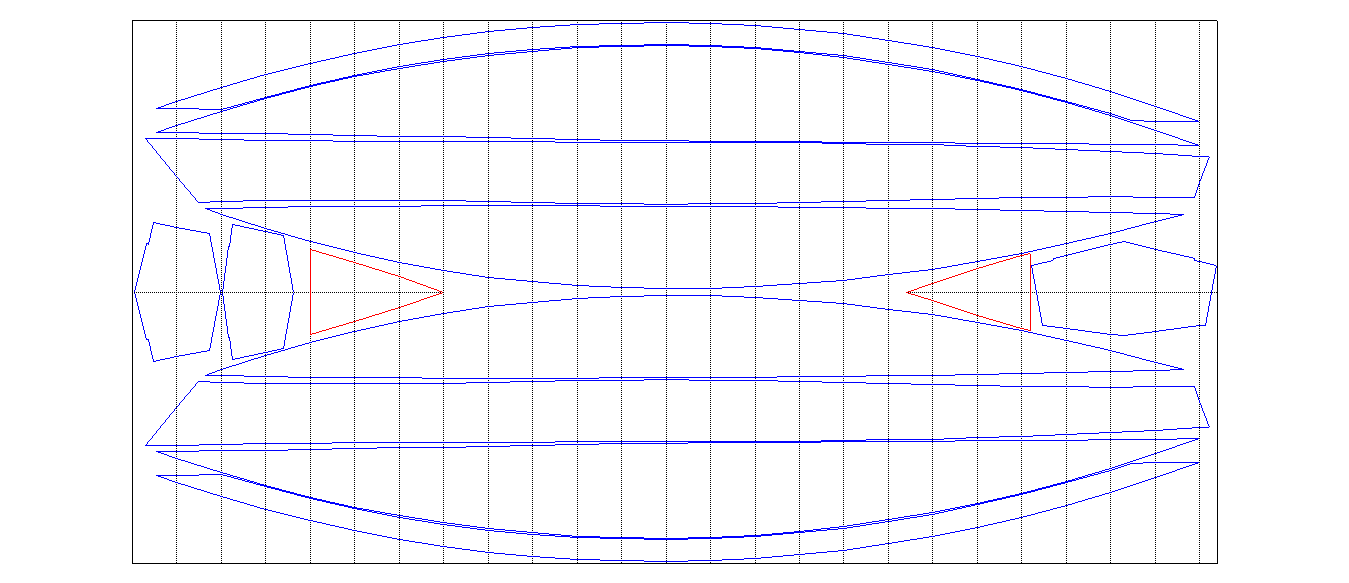
I have re-edited the cut-out design to align most points with 100 mm spacing. The reason for this is to minimise the measurements required to loft the design:
![]()
I have added two breasthooks (red) for the sheer chine join (i.e. "harpin").
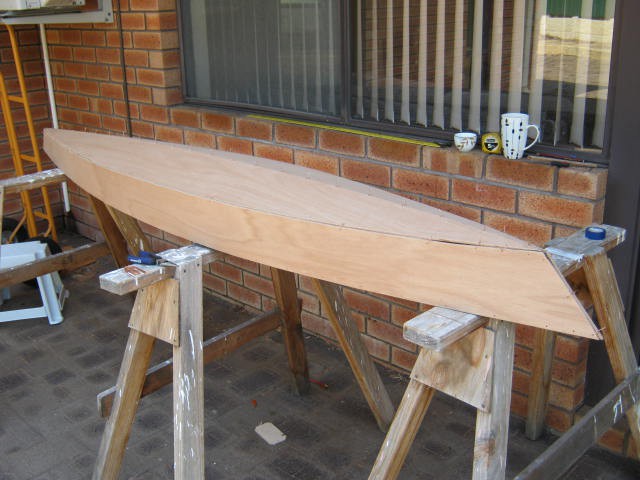
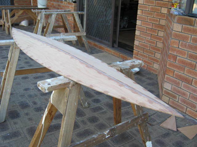
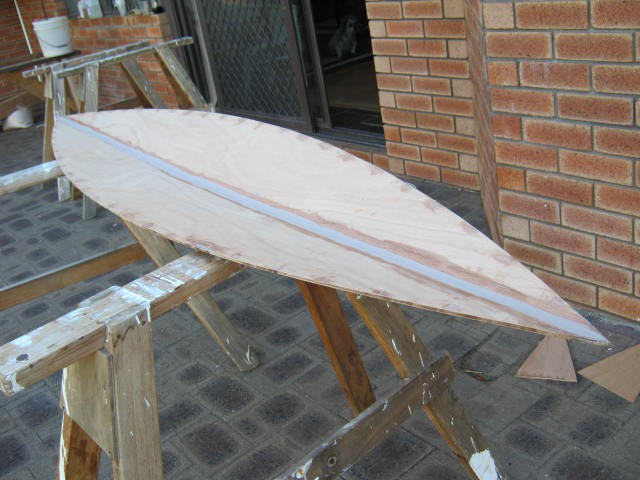
Here is an image of the very first mini-canoe I built some 15 years ago. You can see that I use a harpin to keep it's shape. You can also see the copper wires that stitch the hull together before the seams are epoxied.
![]()
This image shows the epoxied seams (no fibre-glass tape reinforcement was used in this design) :
![]()
This canoe was too small (i.e. tippy) to be usuable.
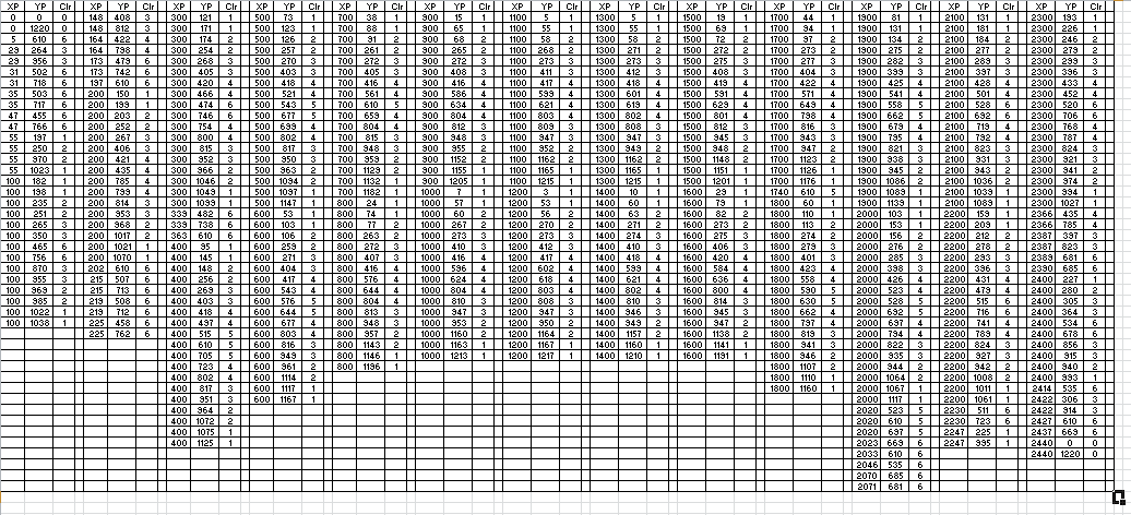
Export Layout Offsets
Finished the export macro. It orders the points by column so that a column is marked at a time (i.e. without moving the measuring tape). With 456 points it is pretty important get the process of lofting efficient.
Here is the code:
Option Explicit
Sub Main
Dim ot As Long
Dim Shape(6144) As Double
Dim num As Long
Dim color As Long
Dim lt As Long
Dim lw As Long
Dim Layer As String
Dim XP(10000) As Double
Dim YP(10000) As Double
Dim Clr(10000) As Long
Dim I As Long
Dim J As Long
Dim K As Long
Dim N As Long
Dim Flag As Boolean
Dim TX As Double
Dim TY As Double
Dim TC As Long

' Get Shape Data
N = 0
ot = dcGetFirstObject("")
While ot <> dcNone
  If ot = dcShape Then
    num = 3072
    dcGetShapeData Shape(1), num, color, lt, lw, layer
    For I=1 to num
      N = N + 1
      XP(N) = Int(Shape(I*2-1)+0.5)
      YP(N) = Int(Shape(I*2)+0.5)
      Clr(N) = color
    Next I
  End If
  ot = dcGetNextObject
Wend

' Sort Data
K = N
While ( K > 1)
  K = Int(K / 3) + 1
  For I = K + 1 to N
    TX = XP(I)
    TY = YP(I)
    TC = Clr(I)
    J = I
    Flag = True
    While (Flag)
      Flag = False
      If (J > K) Then
        If (XP(J - K) > TX) Then Flag = True
        If ((XP(J - K) = TX) And (YP(J - K) > TY)) Then Flag = True
        If ((XP(J - K) = TX) And (YP(J - K) = TY) And (Clr(J - K) > TC)) Then Flag = True
        If (Flag) Then
          XP(J) = XP(J - K)
          YP(J) = YP(J - K)
          Clr(J) = Clr(J - K)
          J = J - K
        End If
      End If
    Wend
    XP(J) = TX
    YP(J) = TY
    Clr(J) = TC
  Next I
Wend

' Export Data
Open "LayoutOffsets.CSV" For Output As #1
Print #1, "XP, YP, Clr"
For I = 1 to N
  Print #1, XP(I);", ";YP(I);", ";Clr(I)
Next I
Close #1

End Sub
AlanX
-
Enclosing the Pontoon
03/15/2017 at 07:28 • 0 commentsEnclosing the Pontoon
This has been a difficult problem to solve. You cannot just fibreglass tape the outside seams as it will leak. Not good. Here is an ideal join (source unknown):
![]()
Note how the yellow filler seals the joint.
One option is to cut holes in the last plank/panel in order to gain access to the inside seam and then patch the holes when done. I did this once and I can say it is still not that easy to tape the inside seam and patch a curved (stressed) panel afterwards.
Another option is to add a chine log/stringer/batten and screw/glue the last panel after bevelling as per this example (source unknown):
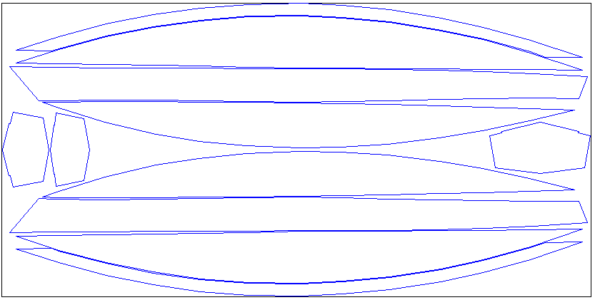
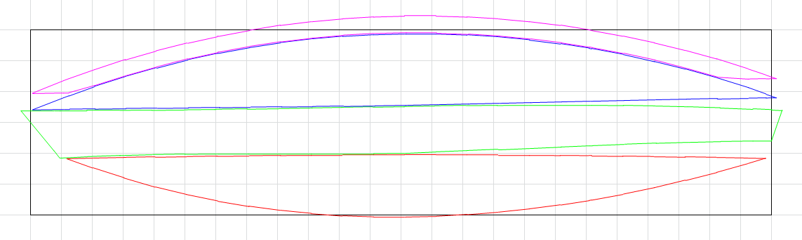
In the end I decide to "lap-strake" the last panel. Here is the unfolded panels (one side only):
![]() The magenta panel is a copy of the blue (top) panel but shifted 50 mm up and trimmed to the blue panel. Instead of using the blue (top) panel, the magenta panel is used instead. After all the inside seams are done, the blue (top) panel is glued/screwed over the magenta panel.
The magenta panel is a copy of the blue (top) panel but shifted 50 mm up and trimmed to the blue panel. Instead of using the blue (top) panel, the magenta panel is used instead. After all the inside seams are done, the blue (top) panel is glued/screwed over the magenta panel.The main problem is that the panels do not fit on a half standard plywood sheet (i.e. the black box) so I will have to shrink the pontoon a little
Updates to the MiniKayakTable Spreadsheet
More updates to the spreadsheet for the above closure method and the inclusion of some DXF export code. The DXF file is as simple as can be but I know not all CAD programs will not be able to read it. As they say: "Not my problem!" as it works with DeltaCad:
![]()
I need to get the data into DeltaCad so I can re-export it for laser cutting, if I decide to build a model. I originally intended to migrate the excel macro to DeltaCad once I had "ironed out" the bugs. I still may if I can workout how to add a table input in DeltaCad.
Here is the central pontoon bulkhead:
![]()
AlanX
-
The Pontoon
03/05/2017 at 13:33 • 0 commentsThe Pontoon
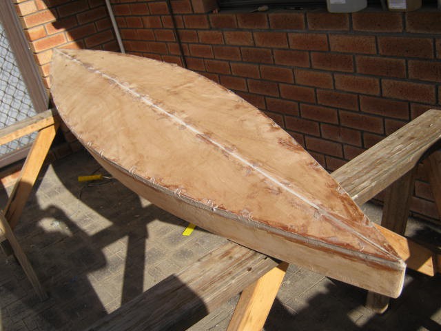
The pontoon design is based on work by Bruce C. Anderson, have a look at his webpage:
http://buckwheat-anderson.com/bcanderson/Boatz/OSKayak/OSKbuild.html
This is what it looks like:
![]()
Here is one side of the unfolded (cutout):
![]()
And the table of cutout offsets (this may be revised):
![]()
I have yet to workout how the how to epoxy the inside of an enclosed kayak?
AlanX
A Plywood Canoe
I built this canoe 10 years ago. It was fun but various design flaws has limited it use. This project is about a salvaging the canoe.

 He says "Give it a try - it is easier than you would think."
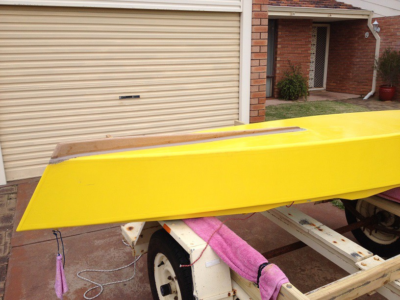


 (source:
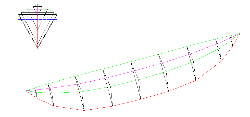


 The magenta panel is a copy of the blue (top) panel but shifted 50 mm up and trimmed to the blue panel. Instead of using the blue (top) panel, the magenta panel is used instead. After all the inside seams are done, the blue (top) panel is glued/screwed over the magenta panel.