Close
0%
0%

Portable Chaos Monkey

Information Radiator, Software Build Monitor

Similar projects worth following
Continuous Integration is a software development practices involving continuously building software to determine if changes have broken the code. This tools heavy approach produces data that can be displayed on LCDs for the team. The tools used often have APIs. This device is intended to be a portable build monitor capable of warning of build failures through various visual and audio queues.

The project is one in a series of build monitors I have built over the years. This one I am trying to make portable so that when someone breaks the build I can move the monkey on their desk and have it irritate the crap out of them as punishment.

I don't plan my projects. I let them grow organically so I don't have good specs and pretty wiring diagrams. Instead I start with an idea and make a few choices that act as constraints. I work the piece out from those constraints making up the design as I go along. I defer making decisions as to what goes where until I have to to maintain flexibility.

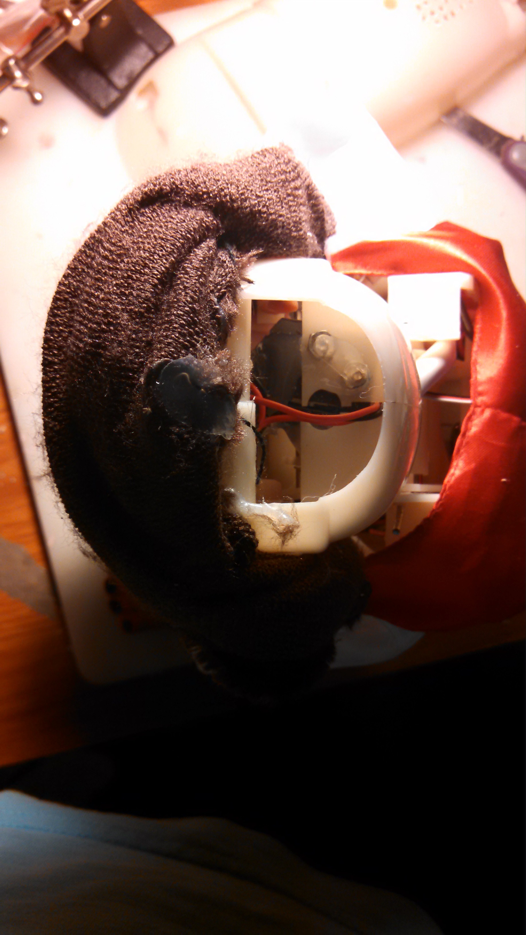
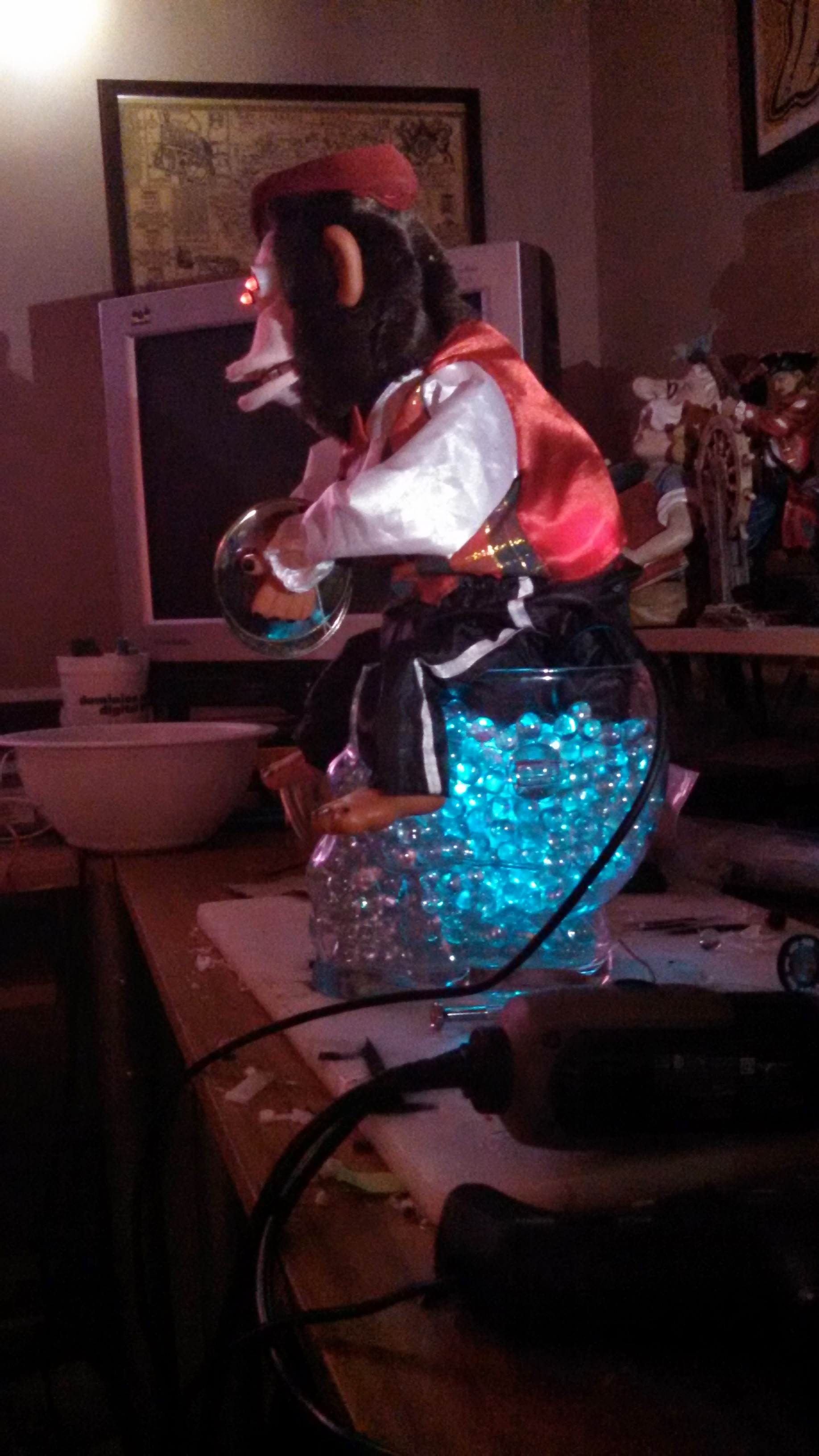
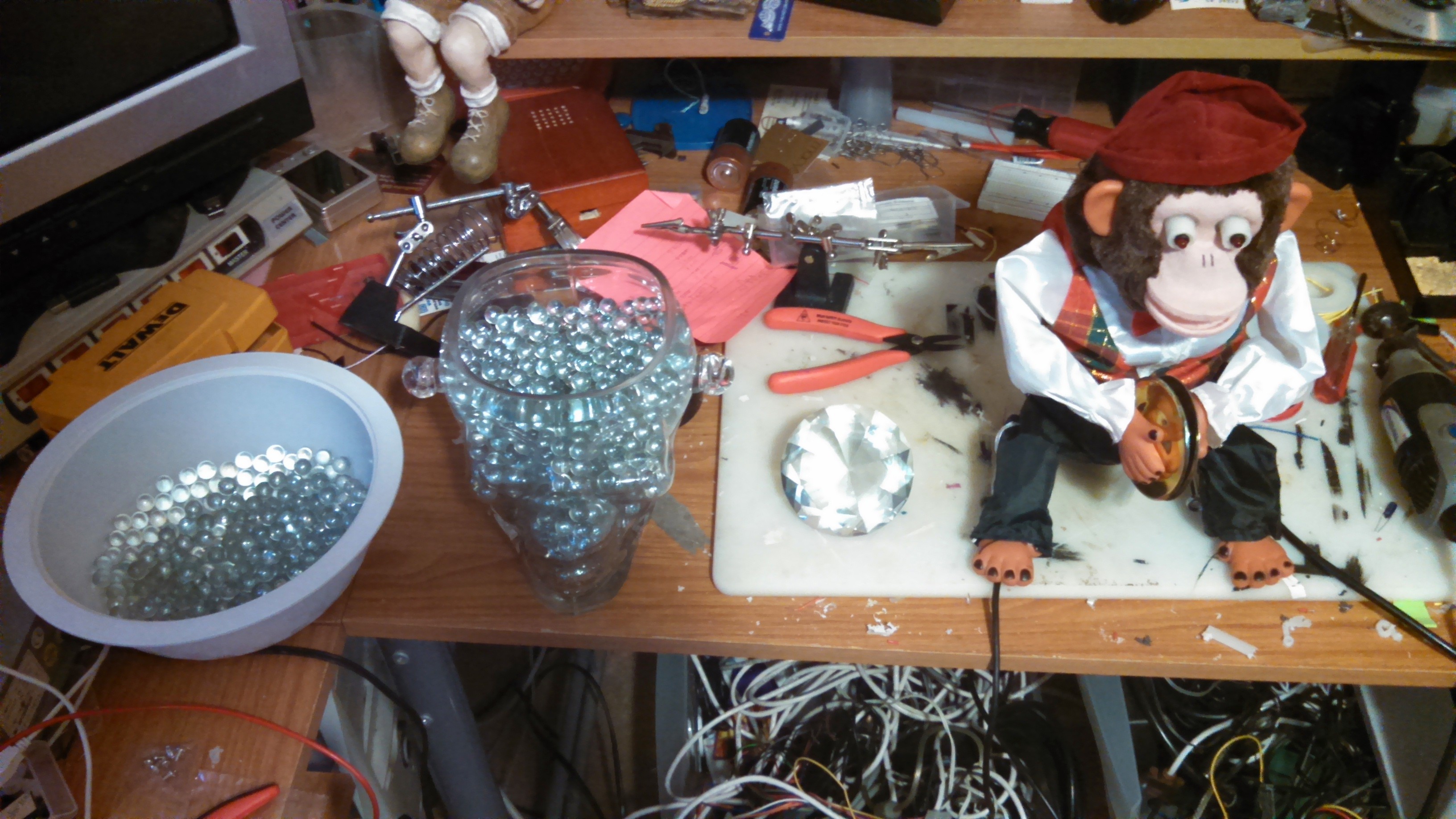
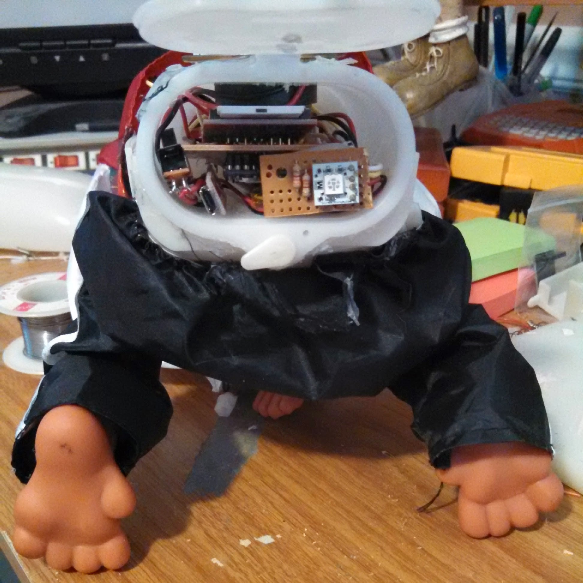
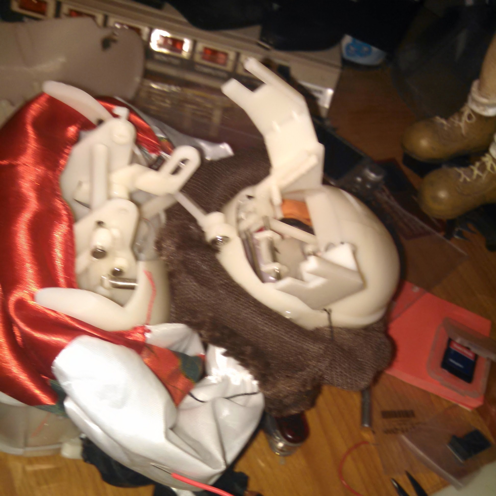
For this project I started with a modern version of a the classic Charlie the Chimp toy. He has two modes of operation: Banging his cymbals and making a nasty grinding sound. The nasty sound is made by grating a piece of springing steel against a gear attached to the same motor used to drive the clapping.

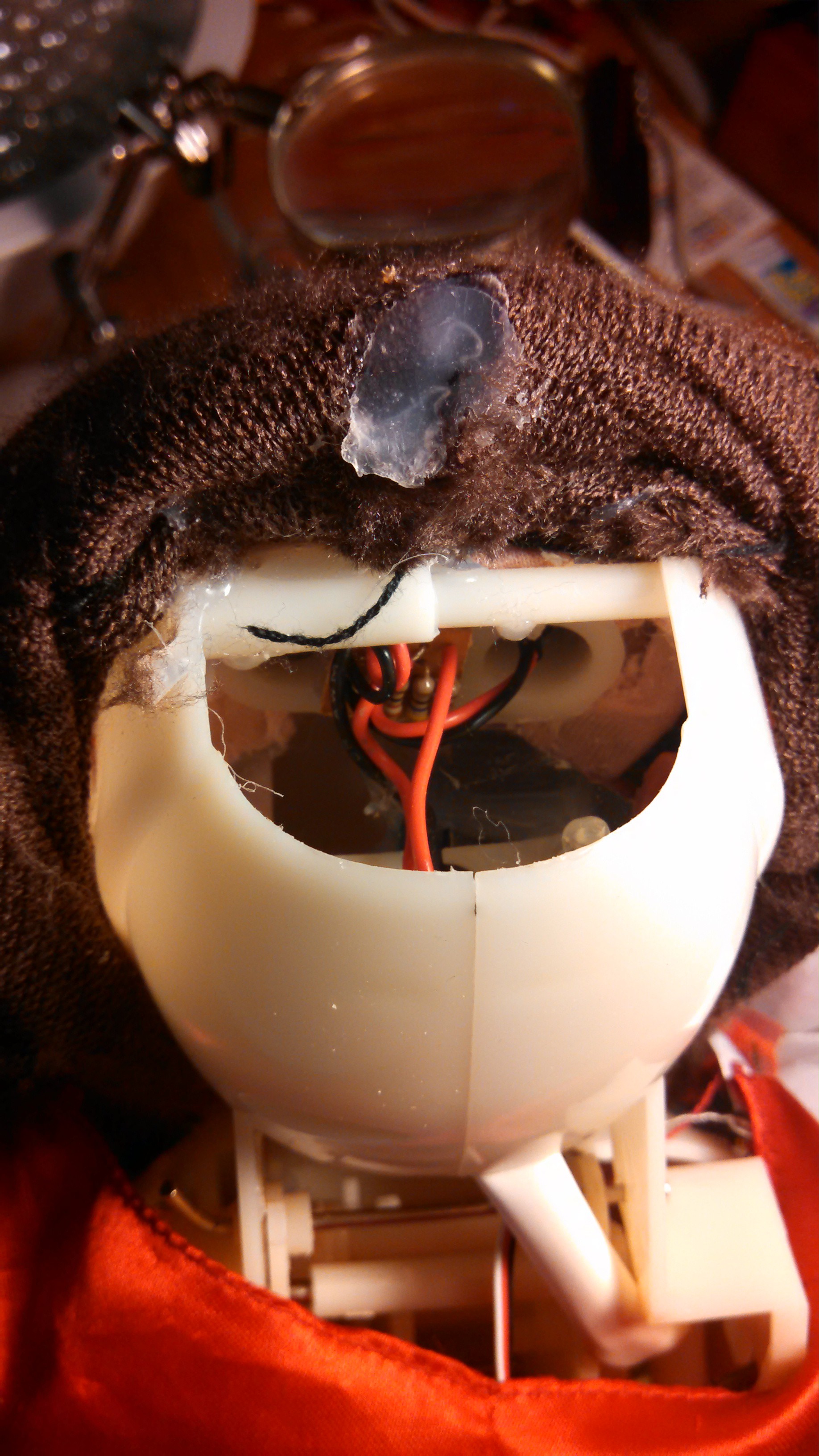
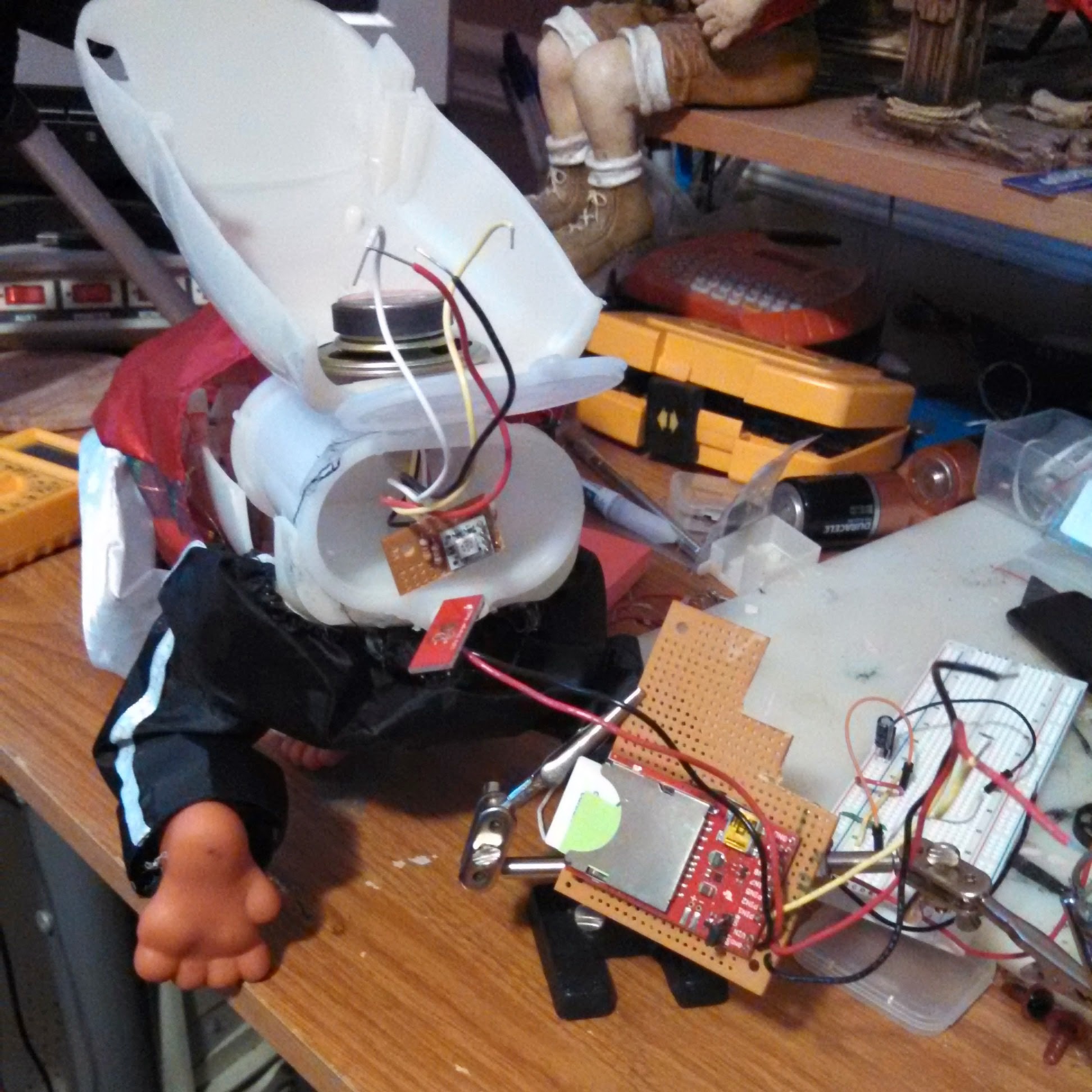
As I started inserting controls into the existing wiring it became pretty clear the current suck from the nasty sound was going to be too much. I also thought it would be fun to replace the sound with a sound card and try to control the mouth using a servo.

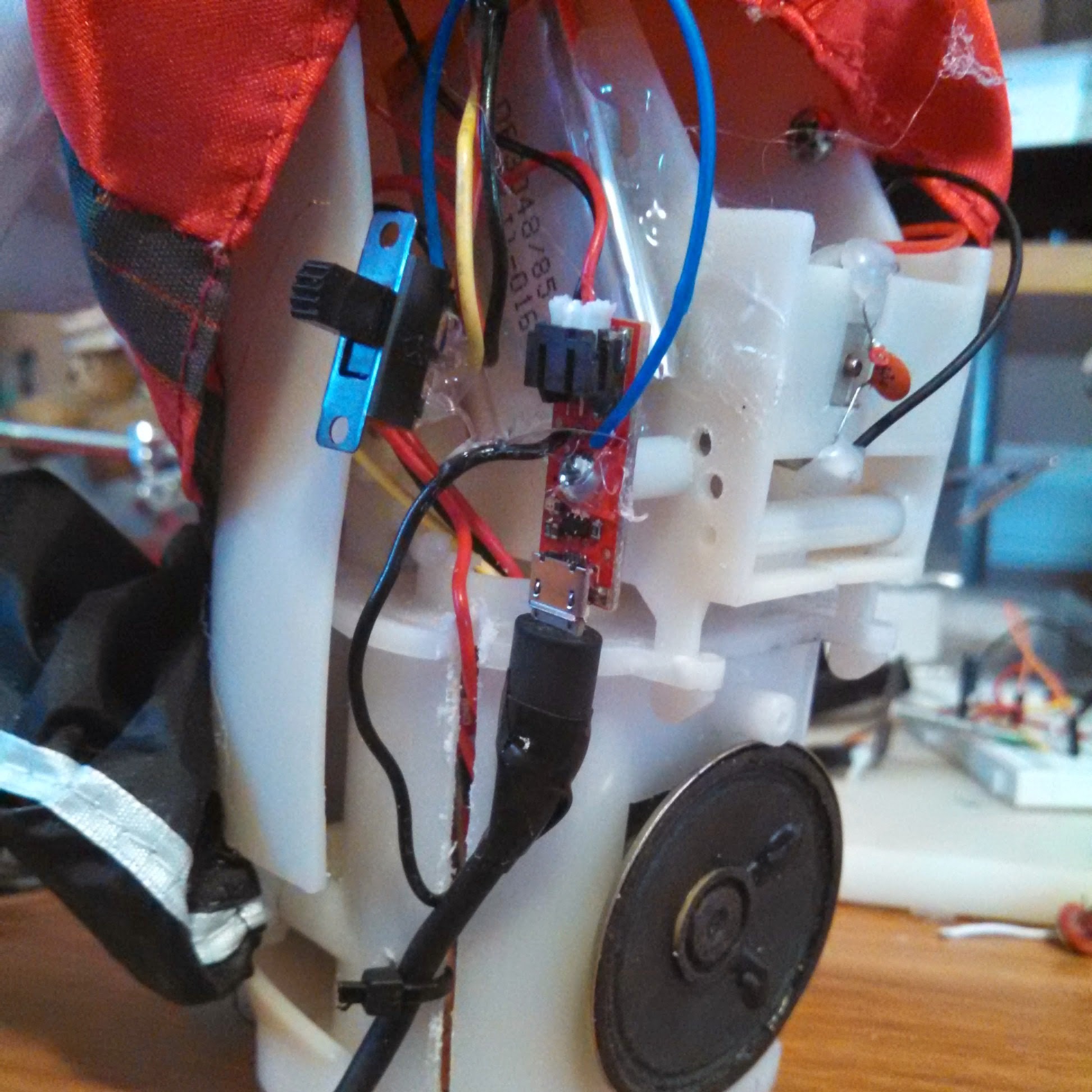
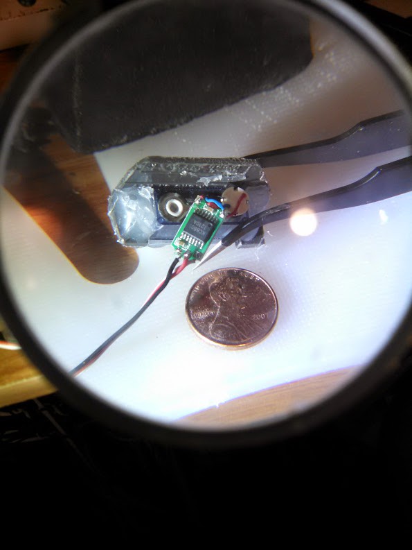
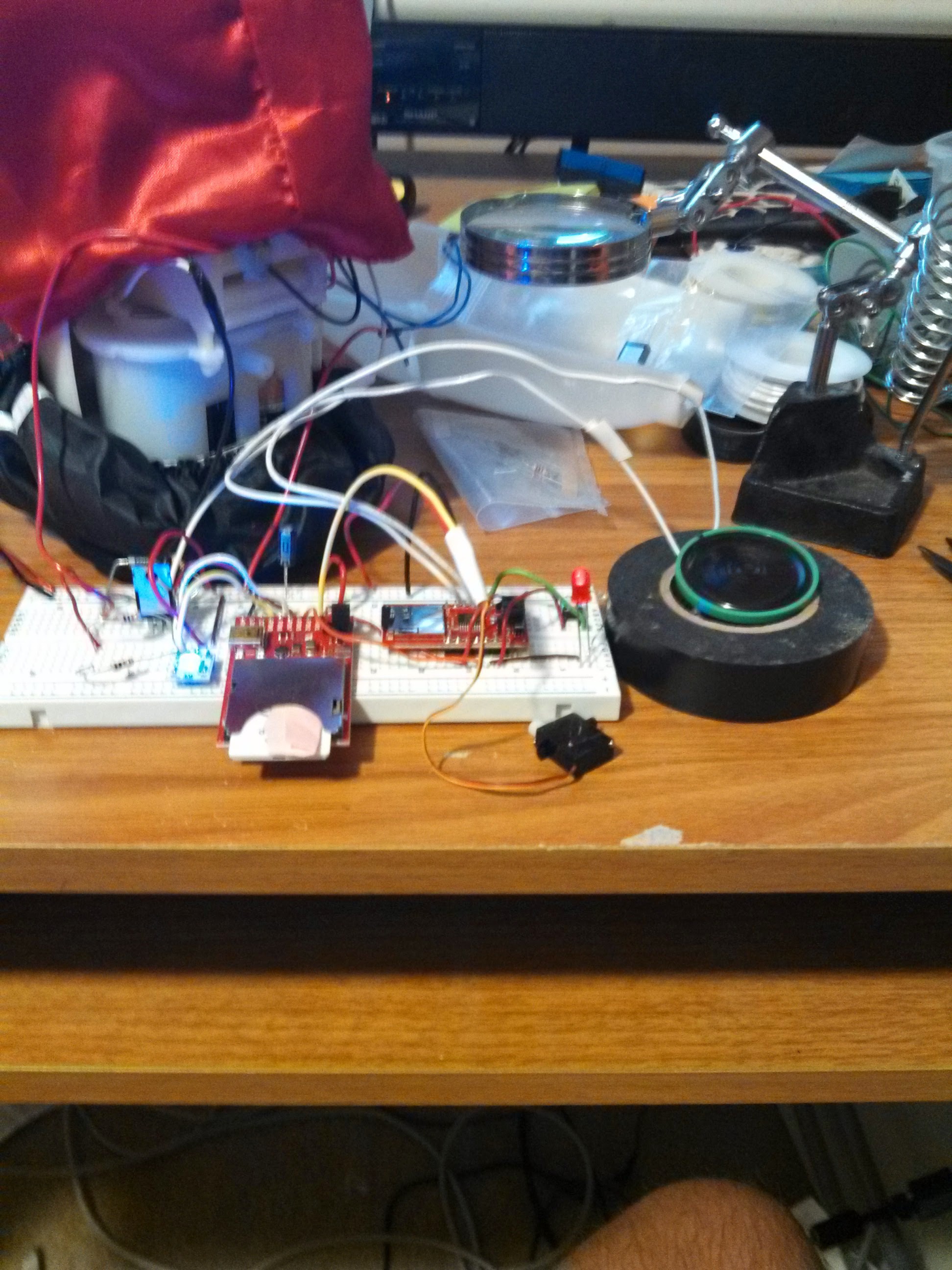
I also needed the device to connect to the internet and was interested in playing with the Electric Imp. So that became another early choice. At the time there were not as many form factors for the Imp. I wish now I had not gone with the SD card version as it only has a few I/O and is physically bigger.

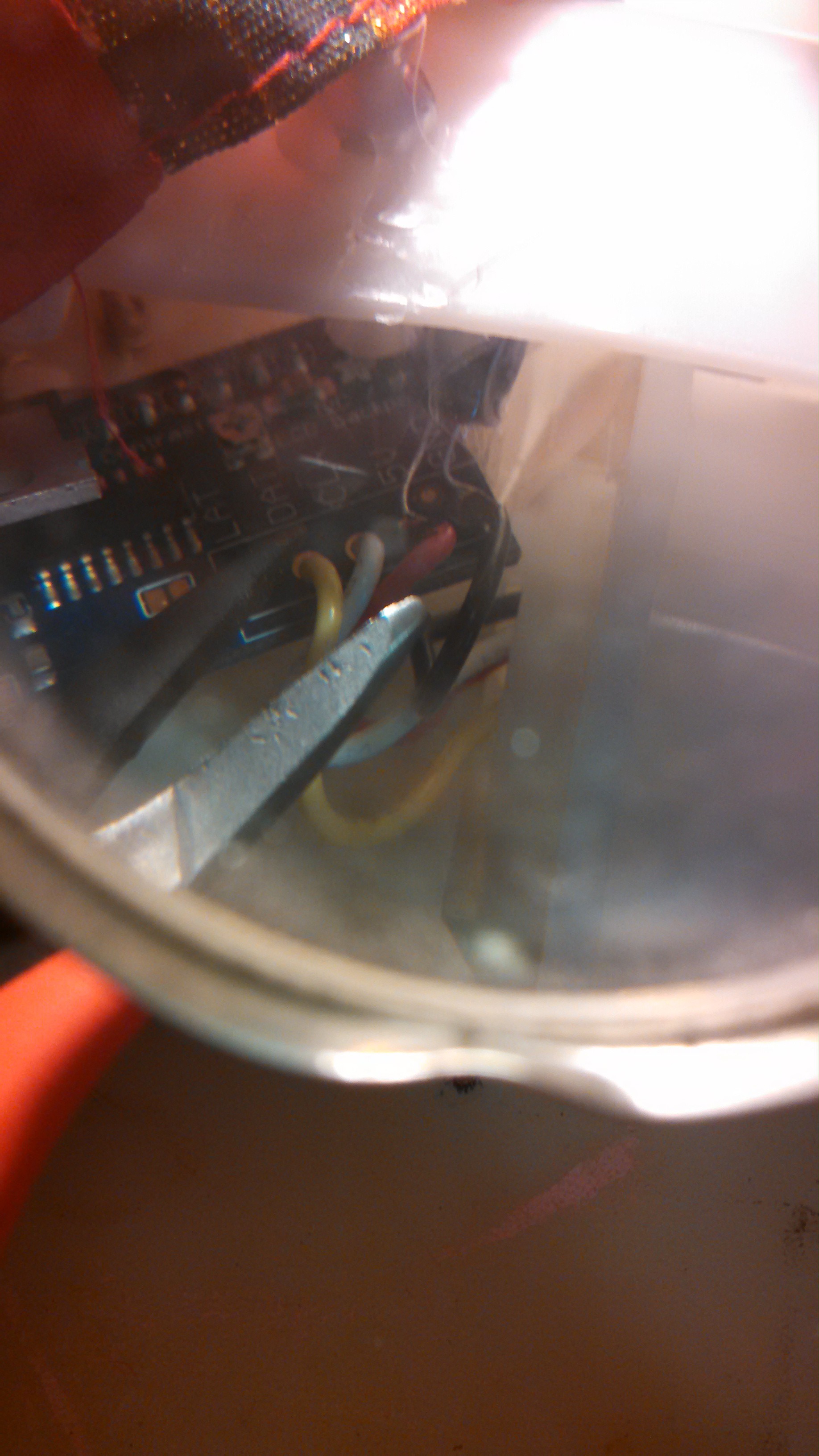
I used an LCD panel controller to give me more I/I via I2C. Not a bad move but it required mounting and more space. I also decided to gut the battery compartment and use it to contain the electronics. This meant using another power sound which led to a lithium battery and charger.

Most idea worked out but the servo for the mouth was a pain. I kept on cutting bit s of original plastic linkages out until I gave up and tried connecting a servo with a home made concoction of plastic servo arms, directly to the bar which acted like an actuator. He currently looks like he is mumbling. I hope to adjust the servo to get more motion before I complete the project.

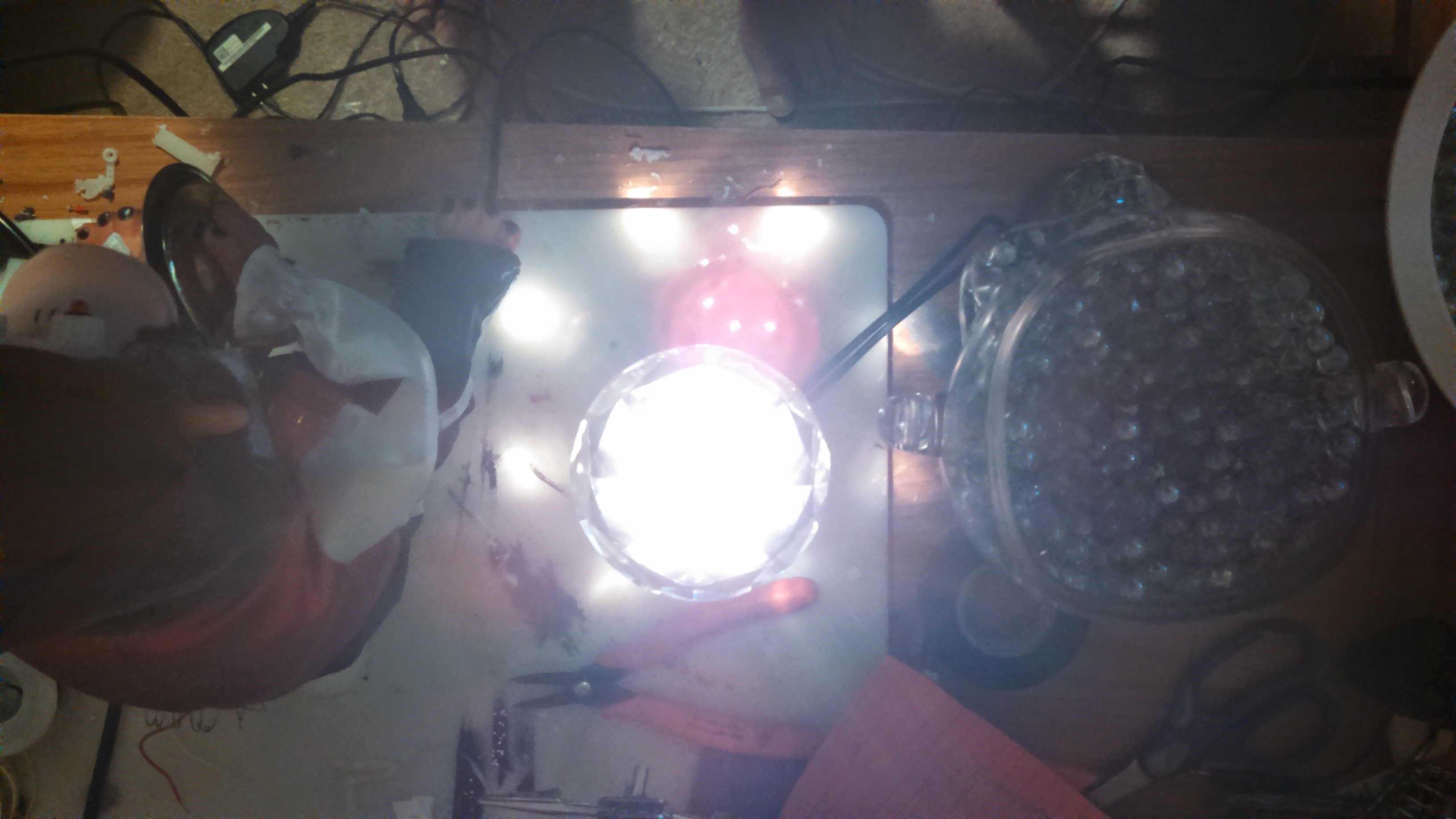
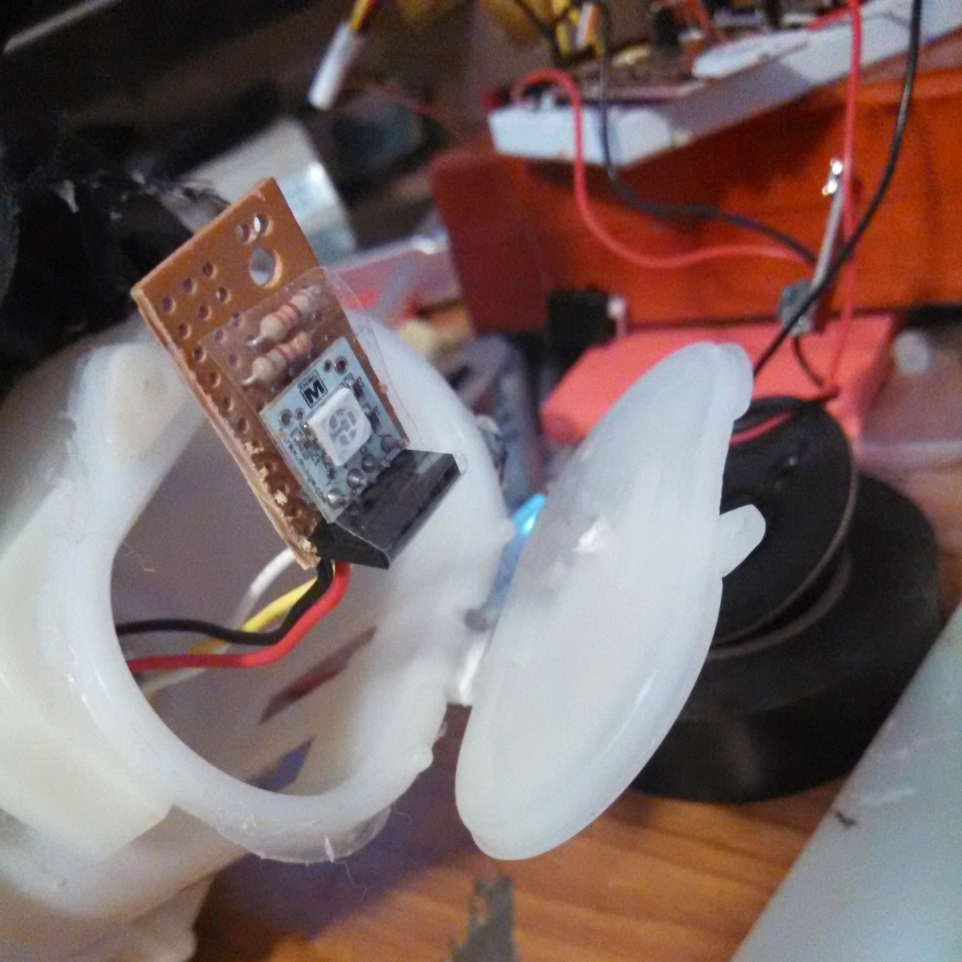
Going with I2C worked well for another feature I wanted which was a controllable light that I could program to change colors according to the state of a build. The Blink M turned out to have preprogrammed modes which were handy in reducing the Imp programming.

I have all but completed the monkey. Integration with the CI software will take some time but the controllable elements are there. I think the Imp will be able to catch Webhooks from the Jenkins server. I can use those to trigger the Monkey.

I have not gotten the power usage on the monkey to where it needs to be. Because the deep sleep mode on the Imp does not reconnect automatically, I'll need to develop an async message queue on the Agent end. Until then, a full charge on the LiPo lasts at max 10hrs as long as I don't run the motor s too often.

1

  • 1 × Sparkfun BOB-11400 Electric Imp Breakout Carrier board for Electric Imp
  • 1 × Sparkfun WRL-11395 Electric Imp
  • 1 × Sparkfun PRT-10217 LiPo Charger Basic - Micro-USB LiPo Charger that also had the 5V USB connector and was mighty small
  • 1 × Sparkfun DEV-09904 MinM - Miniature BlinkM I2C RGB controller
  • 1 × Sparkfun COM-10213 N-Channel MOSFET 60V 30A Used to controll the motor driving the clapping arms

View all 20 components

  • Final Tweaks

    Guy Winterbotham08/17/2014 at 02:25 0 comments

    When I put all together, a problem with motor noise re-emerged. I tired another filter cap on the LCD controller but it did't help.

    Next I neede to try and get the lips to move more. Here are few shots inside the Monkey's head. Not great so you have to use your imagination. First a view into the head showing the screw attaching the servo mount to a flat plastic divider.

    Next, below is a shot of the perf board connecting the eye LEDs with some limiting resistors to the I/O exteder

    Finally a bad shot looking up under the plastic divider in an attempt to show the the servo. The white  wire bundle is the shrink wrap covering the Eye LED wires. Below them the servo wires.

    I got the lips to move a little better but not as much as I wanted. That would have required disassembing the entire servo mount and redrilling. Think I'm done.

  • Moving the Power Pieces

    Guy Winterbotham08/11/2014 at 01:17 0 comments

    Decided it would make more sense to move the power pieces and mount to the side of the motor mount. Good old hot glue will do. I know I'm going to want to up the LiPo from the 850mA to something more like 2200mA to give it a chance to last a while. Since charging was also going to be a deal I decided to add a permanent USB cable so the charger would not be getting yanked about all the time. In a moment of serendipity, the original power switch I added back in ended up being close to the original mounting so mount it back I did.

    This shot also shows the speaker squeezed into the battery compartment. I drilled some holes in the back shell to let the feabile sound from the unamplified 3.3V PWM output of the sound module.

  • All lit up and nowhere to go

    Guy Winterbotham08/11/2014 at 00:20 0 comments

    The picture shows the effect of the refraction and disbursement. Not very bright but mot bad for an IoT device with this much going on. I have the eyes turned on. Here I have set the color to blue and green for an aqua color. As you can see its a bit of a crap shoot as to where the light goes. Here the lower front does not get much penetration.

  • Playing with light

    Guy Winterbotham08/10/2014 at 23:58 0 comments

    I wanted the monkey to be separate from the base so that the effect of the light shining out of his bum was a little magical. Look mum, no connections. To do that I need to be able to difuse the light. In Build Monitors consisting of orbs, that usually means some form of frosting. I considered frosting the glass skull. I came a across some pre-frosted pebbles at a craft store. They did a good job, but shining a light through them at the store showed the light would not penetrack far.

     I settled on clear glass balls that could allow for refraction of the light. I also found a large acrillic diamond at the store that I saw could also refract the light outward from a focal point. I'm sitting the diamond flat side down on a flashlight so you can see the distribution and limited reflection back onto the table.

    I jammed the diamond into a skull full of balls. The monkey with Blink M facing downwards sits on the diamond and the RGB light gets distributed. Here the flash gives you a sense of the distribution.

  • Perf Board - Butt Ugly Mounting

    Guy Winterbotham08/10/2014 at 23:42 0 comments

    So I'm only ever making one of these. I never repeat (unless someone wants to throw me money) and so perf board will do. No I'm not showing all my crappy wiring. Basically the imp goes on one side and the VM module on the other.

    After I had everything mounted and connected I trimmed the perf board. I always deferr decision like when to cut and trim to the last responsible moment to give me options. In the picture above you can see the Imp module, the Blink M and the back of the LiPo charge. Below I jameed evenything up into the compartment and got it all to fit.

    I then decided to move the power outside so that there was enough room to push the Blink M back in. It was clear by now the LiPo was not going to last as I wanted so I need to add a USB cable as it would remained plugged in more than I wanted. In this shot you can see the VM module on the other side of the Imp module.

  • Loading up the Blink M

    Guy Winterbotham08/10/2014 at 23:35 0 comments

    I mounted the LCD to the outside of the battery compartment. I routed the I2C wires so they could eventually be attached to the Blink M and then the perf board holding the Voice and Imp modules.

  • Always keep your crap

    Guy Winterbotham08/10/2014 at 23:31 0 comments

    I have always kept old bits of electronics to use some day in the future. This time around they came in handy. I found an old cellphone with a 4G SD card I could use and an old remote that I chopped up to make a servo mount.

  • Be kind to your servo

    Guy Winterbotham08/10/2014 at 23:28 0 comments

    I found a servom that operated at 3.3V but is was so small it was impossible to attach an extension to the tiny arms in order to engage the rod that pushed against the mouth to make it move. I upped the size of the sero but the rough handling to get it to fit caused it to fall apart. I need to get my eyes checked but at least my hands are still steady enough for this work.

  • Hacking the head

    Guy Winterbotham08/10/2014 at 23:25 0 comments

    This part was a PITA. Basic idea was in some way to attach a servo to some part of the mechanism that drove the movement of the lips. Unhacked, when you hit the monkeys head, it pushs down a rod that switches the direction of the motor and engages gears that:

    • Move the mouth
    • Make the eyes move in and out
    • Make a nasty screeching sounds by grating some spriny steel against a metal gear.

    I tried several different linkages but in the end just kept cutting linkages until I finally found enaging a rod was the easiest way.

    This pic is not that great but shows the head disengaged.

    By going for the rod I had to remove the linkage that moved the eyes. I made up for that by replacing them with LEDs that I could then control with the LCD panel.

    That's how I roll. make it up as I go. More fun, more challenge. No frustration of a plan not working as there never was one.

  • Bread Boarding the VM Module

    Guy Winterbotham08/10/2014 at 22:06 0 comments

    Pretty straight forward. After figuring out the majority of lines were internally held high I just needed. Power and signal (clock and data). It would have been nice if the module would have been I2C. It suck two precious I/O for signal and data plus I feed the Busy signal back into the IMP so I could use it to trigger the servo. You can see the Blink M which hung off the I2C bus nicely. It had the added benefit of preprogrammed modes which woul map pretty well to what the Jenkins build server did with using colored states for build status.

    The speaker was an early choice but was too quiet so I went with a larger device.

View all 14 project logs

  • 1
    Step 1

    All this was unplanned and custom built as I went along. So as far as instructions.... nothing to see... move along.

View all instructions

Enjoy this project?

Share

Discussions

Guy Winterbotham wrote 07/22/2014 at 21:56 point
Jonathan
I have a larger stationary one that has a pirate voice to abuse those close by, a synth voice to speak the names. It also abuses them over IM and Tweets their failures. It also runs a CI game that scores check ins and code quality. It has a screen with a scoreboard.
This one I hope to make portable. It has sound playback via a small soundboard but not voice synth. I'm going for low power.

  Are you sure? yes | no

J Groff wrote 07/22/2014 at 19:35 point
Does it report on who broke the build and then have a Gilbert Gottfried voice synthesizer to publicly shame them?

  Are you sure? yes | no

Similar Projects

Does this project spark your interest?

Become a member to follow this project and never miss any updates