 SHAOS
SHAOSIn order to test 3niti alpha with front panel you can do steps below:

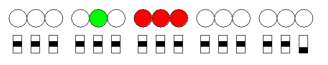
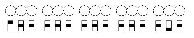
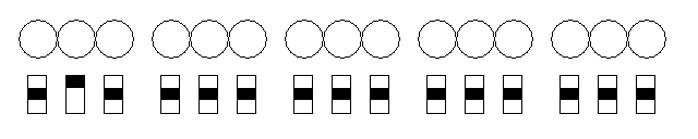
Power ON with all switched in neutral position (O) should gives you all indicators OFF (all O) and 3niti alpha will stay in PAUSE mode. Then you move right switch (S/G) down that should start program running (Go), but because all memory should be zeroes at this point (OOO) it should perform ADI 0 instruction and address indicators (left 9 lamps) will start count up with step 2:
(if you already have something at OOO OOO OOO and later then this test will actually launch that program)
Now power OFF and power ON 3niti alpha again (with all switches at neutral position)

While in PAUSE mode move left switch up:
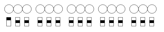
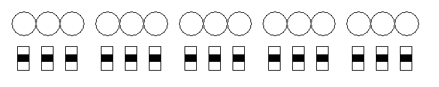
It will set address switches to POO OOO OOO - now move switch I/M up:
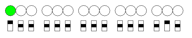
It will move chosen address to program counter (PC) and left 9 ternary lamps will indicate this change (see above) - in the same time previous value of PC (OOO OOO OOO) will be stored internally. Now move switch I/M back and PC will stay with that address:
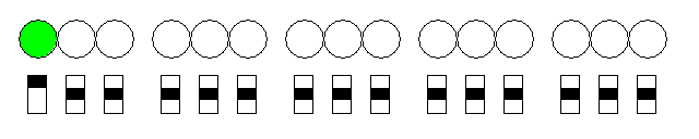
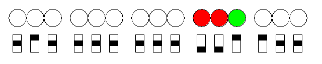
Here INTERRUPT was performed to force 3niti alpha to jump to specified address and to store previous value of program counter to know where to return. If you move I/M down it will jump back to "main" program by restoring PC value (OOO OOO OOO):
Now test read/write capabilities - power OFF and ON with neutral position again:
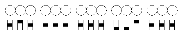
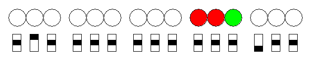
Set address switches to OPO OOO OOO:

Then set data to write (NNP):

Writing is performed by moving switch W/R up:
As you can see data indicators started to show new value - if now you return switch back to neutral position, indicator will switch back to showing value from memory cell where program counter points:
Here it's OOO OOO OOO and OOO. Move data switches back to OOO:
Now you may try to read value from OPO OOO OOO by moving switch W/R down:
NOTE: for latest firmware of 3niti alpha simu1 only 2 paragraphs (27-triad blocks) of memory are implemented:
OOO xxx ABC - for "read-only" (stored in EEPROM of PIC16 and writable only through serial connection by PDBL console commands) and
OPN xxx ABC - read-write memory, writable from front panel (stored in DATA registers of PIC16).
I'll extend memory in near future (external memory should be used for that purpose - it's already there on the board - only software support is required)
Discussions
Become a Hackaday.io Member
Create an account to leave a comment. Already have an account? Log In.