 drojf
drojfCircuit
There isn't that much to say about the circuit
itself as the AL3050 makes things so simple - I just followed the
schematic provided in the datasheet . The AL3050 has an internal MOSFET
and internal diode, so very few components are needed - an inductor to
boost the voltage, a current sensing resistor, and some decoupling
capacitors (and the LEDs you want to drive of course). The AL3050
datasheet recommends a max output current of 40ma at a max voltage of
30V. This doesn't sound like much, but with 8 leds as per this
configuration it's plenty bright for a torchlight.
The AL3050 also has a special CTRL pin which is different to the dimming pin on most other parts. It has three modes:
- As an ENABLE/DISABLE pin
- As a standard PWM Dimming pin
- As communication pin to set the brightness to one of 32 values
See
the datasheet for more information on how this works. In this case I
shorted it high underneath the board to make sure it stays on (HIGH =
ON).
I have chosen to place 8 LEDs on the board. Assuming a
worst case forward voltage of 3V, the 8 LEDs would drop 24V, which is
below the max voltage threshold of 30V. You really need either high
voltage LEDs or many LEDs in series to get the best out of this chip,
otherwise the total light output will be low. I used the cheapest, but
still very efficient LEDs I could buy off Digikey (they're incredibly
cheap, I might add). Note that Digikey has two sections for LEDs - the
"indication LED" section and the "lighting LED" section - you will want
the "lighting LED" section to get the correct type of LEDs for a
torchlight / general lighting.
Fabrication
The
PCB was ordered from PCBWAY. I had never soldered QFN/DFN type packages
before, and assumed that I could heat the inner heatsink pad of the
package from a pad nearby it - this didn't work at all. The inductor's
pads were also unreachable with a soldering iron. I ended up just
soldering it using a hot plate style heater.
I also had problems telling where PIN 1 was due to the poor lighting on my workbench. Aligning the DFN was a pain as I had made the pads extra long for "hand soldering" which actually made it harder as the part would not "auto-align" due to surface tension. Due to these problems, I had to reflow it twice or thrice, as I had shorted some of the pins together (I tested for shorts with a multi-meter before powering it on). In any case, you must be comfortable soldering DFN packages if you want to build this breakout board, probably using solder paste and an oven/hot air pen.
Results
I haven't tested efficiency yet, but it does work well powered off 3 AAA batteries. The device will operate from 2.7-5.5V, so you need at least two AAA batteries to drive it (or one lithium ion type battery).
 Yann Guidon / YGDES
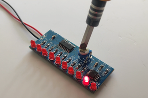
 endevor100
 Hulk
Hulk
Note about the digital dimming: my datasheet of the AL3050 states two different "Device Address Byte" values. On most places it is 0x72 but the right value 0x58 is hidden in a single location inside the text. It took me a lot of time to debug.
The digital dimming is not suitable for a smooth fade away. The steps are well visible at low brightness level.