 Metalnat
Let me tell you of my journey of getting to this point:
It started off well enough with studies and following the path of Getting to Blinky with @Chris Gammell. Then after that going through KiCad Quickstart Guide. With those two sets of videos followed I was able to fumble through some board design.
I started with a simple goal. Take a teensy 2.0 footprint and break out 4 IO pins to buttons with pullup resistors and ending on the board with a wire-to-board JST connector. Then add 4 analog (3 pin) jst connector to 4 other IO. This time adding the resistor on the vcc line, in case end used shorts the vcc and gnd wire together. This led me to this first attempt:
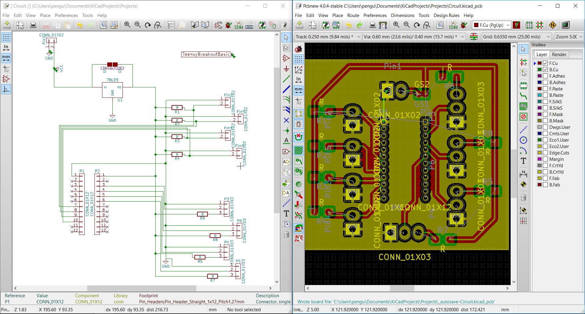
In the top left you will see where power supply feeds system. Then a 5v voltage regulator but if I happen to feed a regulated 5v source I have to option to jump the two pads and bypass the regulator. Then it's my button setup. followed by my analog in setup. One thing many of you may have noticed is that my traces on the right do not connect to my SMD (Surface Mount) resistors. There is a simple reason for this..... I did not know yet how to "flip" the component to backside. Nor did i know that pressing the "B" key with the fill area tool selected would refill my ground plane.
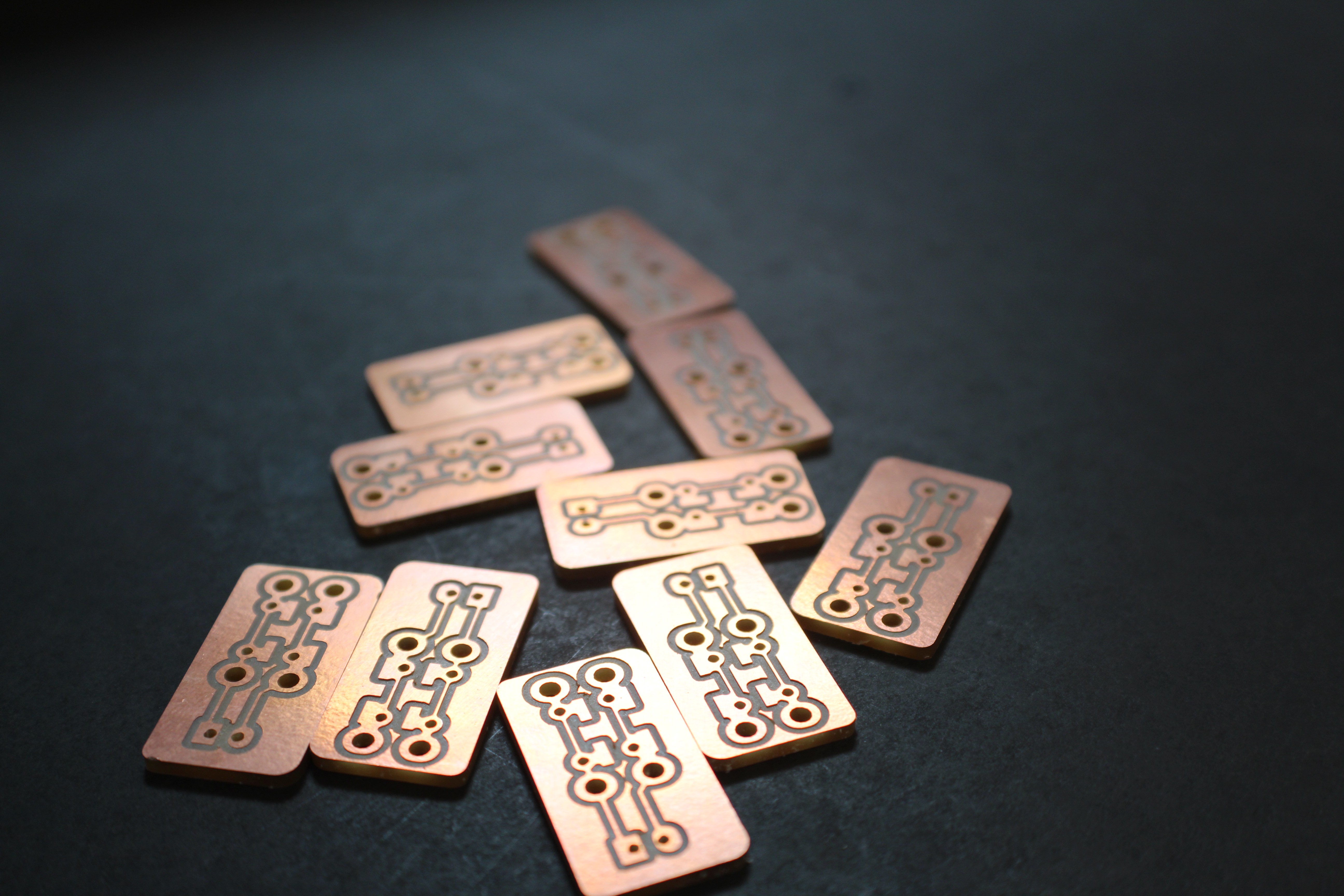
Being anable to fix this I deleted the file completely and started over. The second attempt went by a lit faster and I made these:
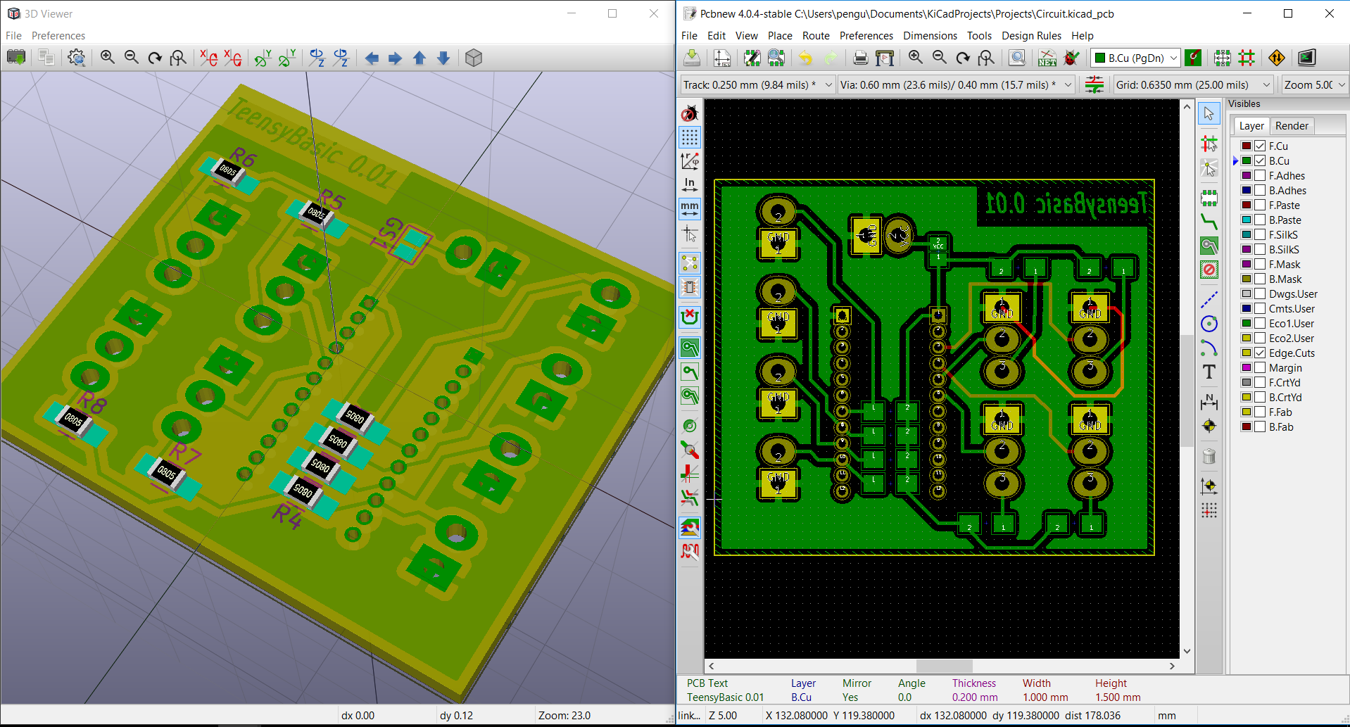
Holy crapcakes! I found that KiCad has a 3d view tool built in. so cool right?.
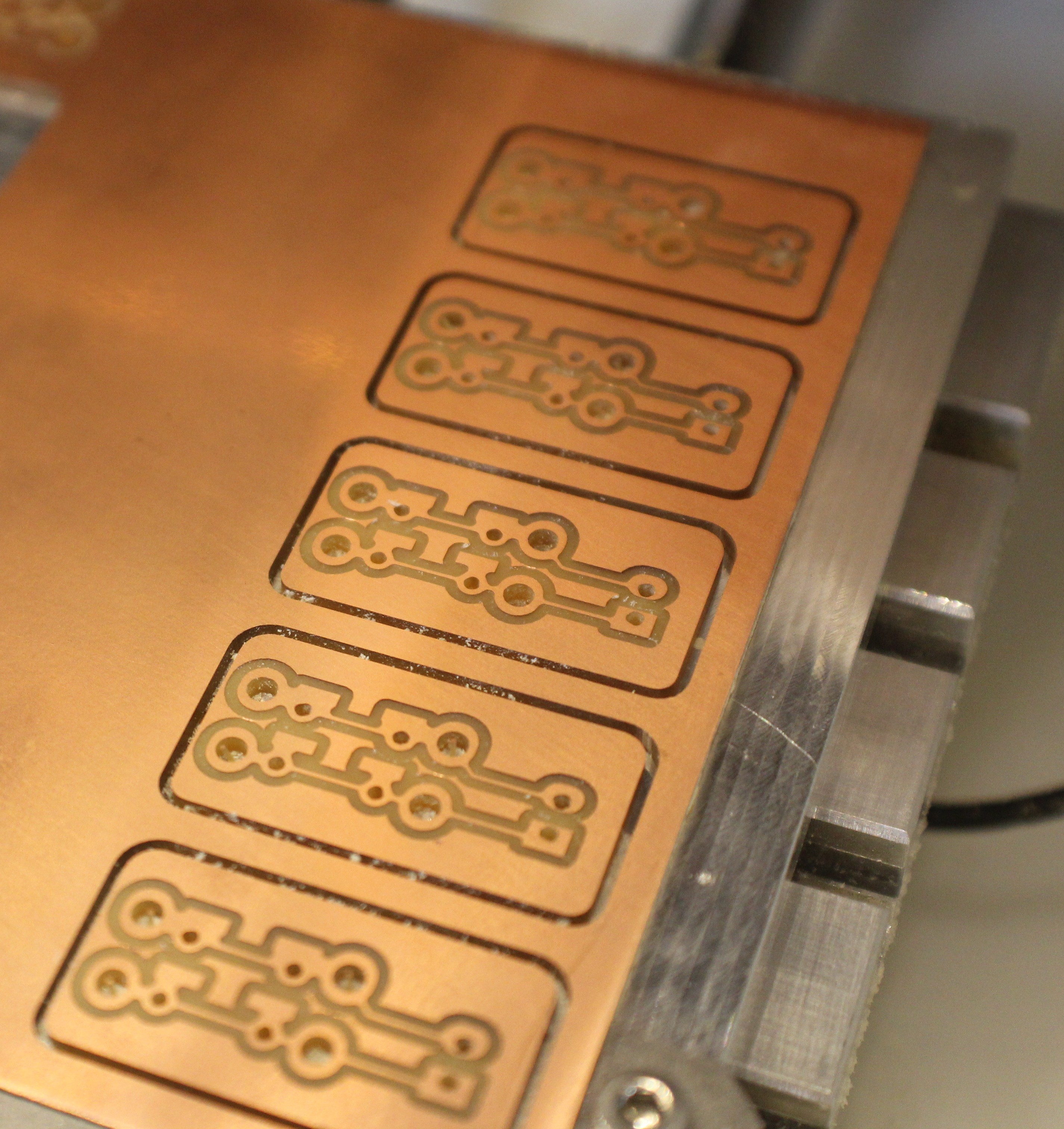
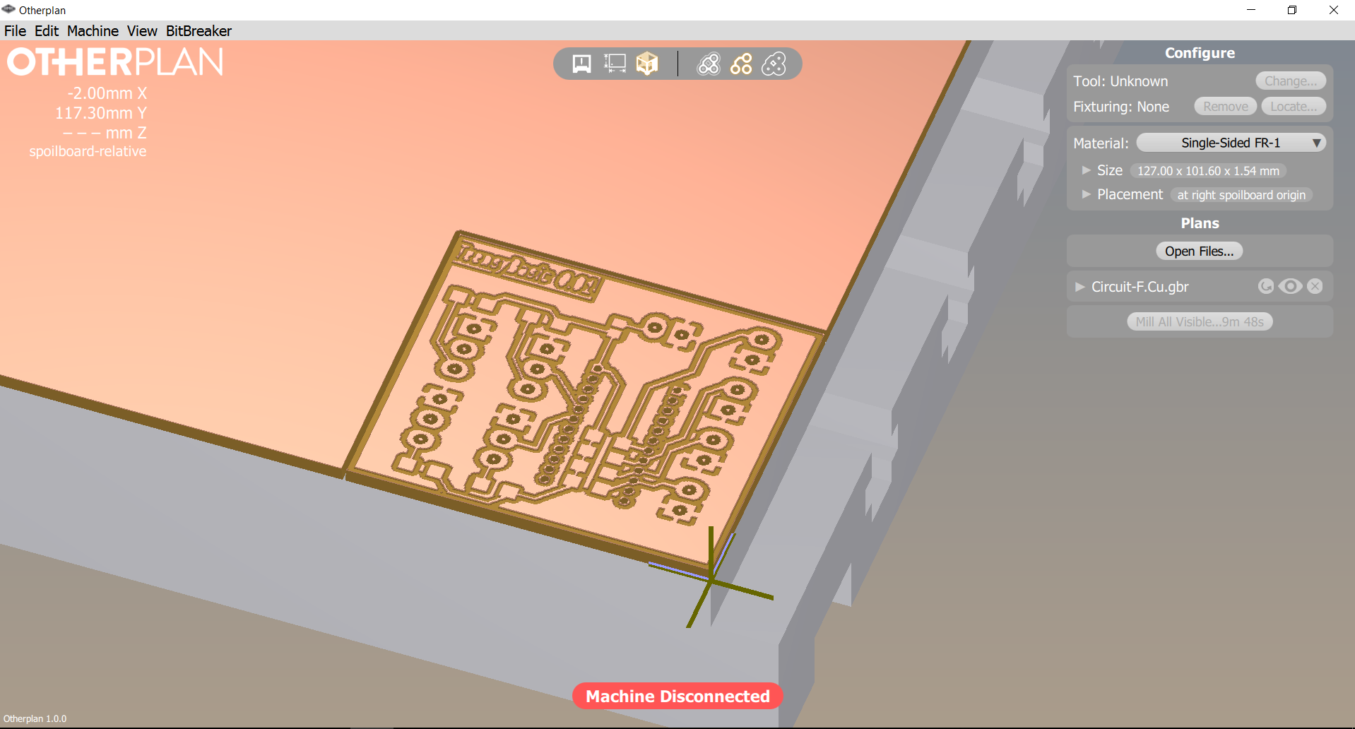 And after some playing around with the OtherPlan software I was able to generate a setup for cutting. And this began my journey into the physical world... I mean other 3d printing and that birth thing.
My first casualty from ignorance. I had thought that since the machine knew it's width of tool, and the jig placement could only be set by the two holes at the front of the other mill, that the tool path would know an offset for placing board layout inside of the safe area for these tolerances. This is not the case.... Also since I was about to learn the first valuable lesson i was hoping for..... real world measurements and interference:
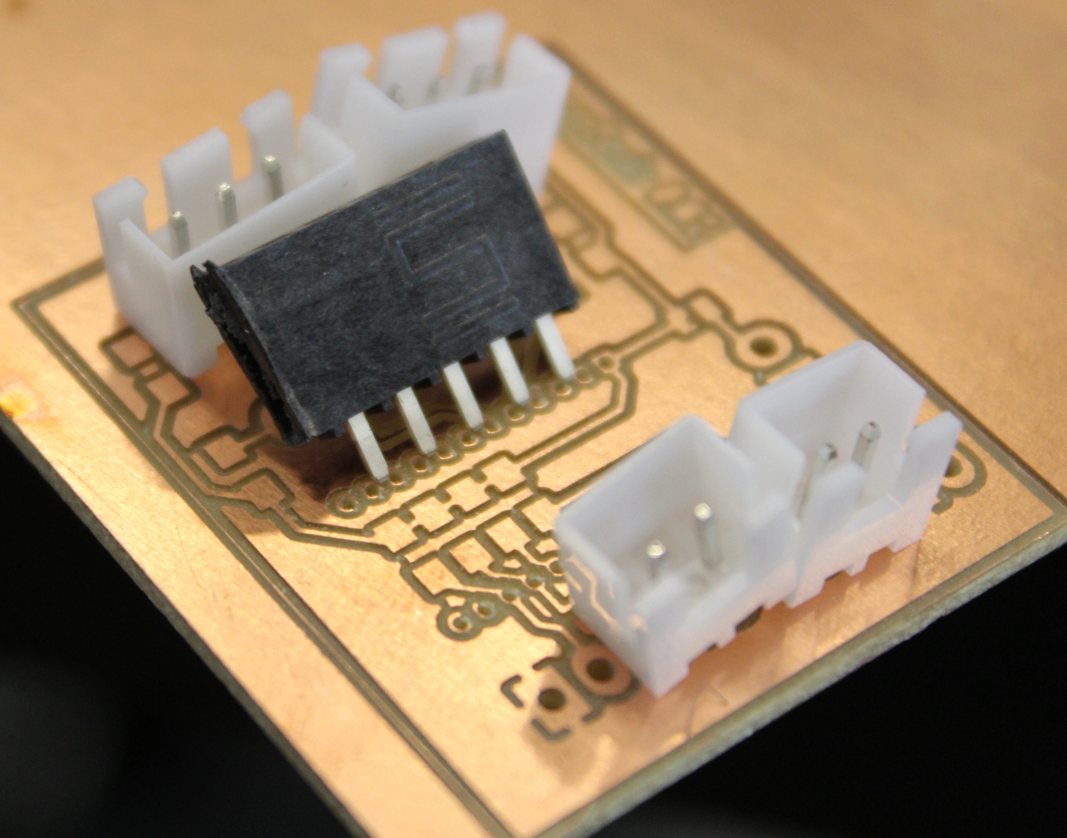
Even though the JST connectors fit right into their places.... they don't fit right next to each other. Turns out, the footprint i used doesn't have the right spacing for the outline of the plastic parts. Also I had made a mistake with choosing my header spacing... by double. It's easy to select spacing that isn't the 2.54 spacing that I now know that i needed. On a good note, the 0805 components line up perfectly. so woot for that. At this time I had enough info to work on this board at home so I could be ready for my next day at the design lab. So to best use time at space I hop on to a more simple board concept.
The general Button V1 board:
- Two pin by way of JST connector
- Allow for 6mm button
- Allow for 12mm Button
- Allow for SMD button
- Not break any more bits.
The next little board i make schematic for, draw out circuit, and have on the mill within 30 minutes. Wow I feel really good and accomplished at this moment for sneezing out a simple design. This feeling was short lived however as my next step.... break a bit. Seriously!
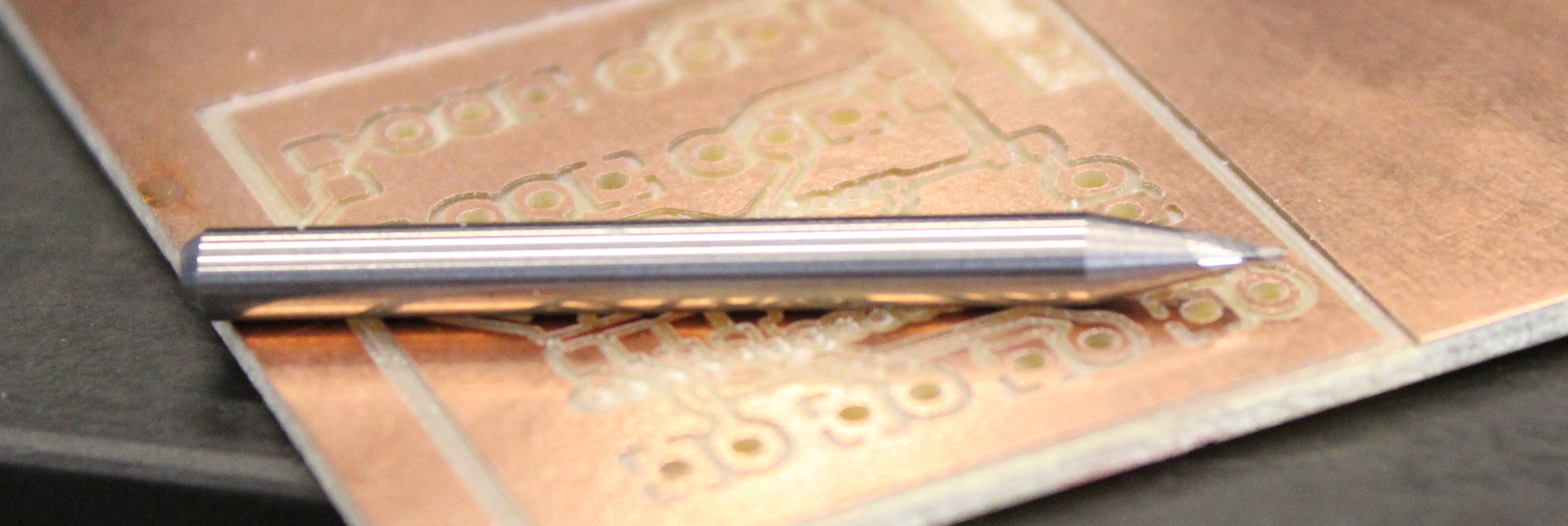
My previous experience on this machine was that first thing it would do was bring bit to middle front and ask for confirmation on bit type/change opportunity. Then it would go to the right and home just off of the side of the the material. Thinking this was a beginning gcode type of thing I go ahead and change the bit and press the start milling button. What i didn't know is that i had the order different than the machine thought and since i did not specifically initialize the "change bit" opperation by top right button press, and it thinking it was still the previous bit and what it wanted, it just went in and did a plunge right into the copper board. This is when I asked what i missed and was informed of the button on the top right. So bit two down and another lesson learned.
Then i was able to start cutting my first button board.
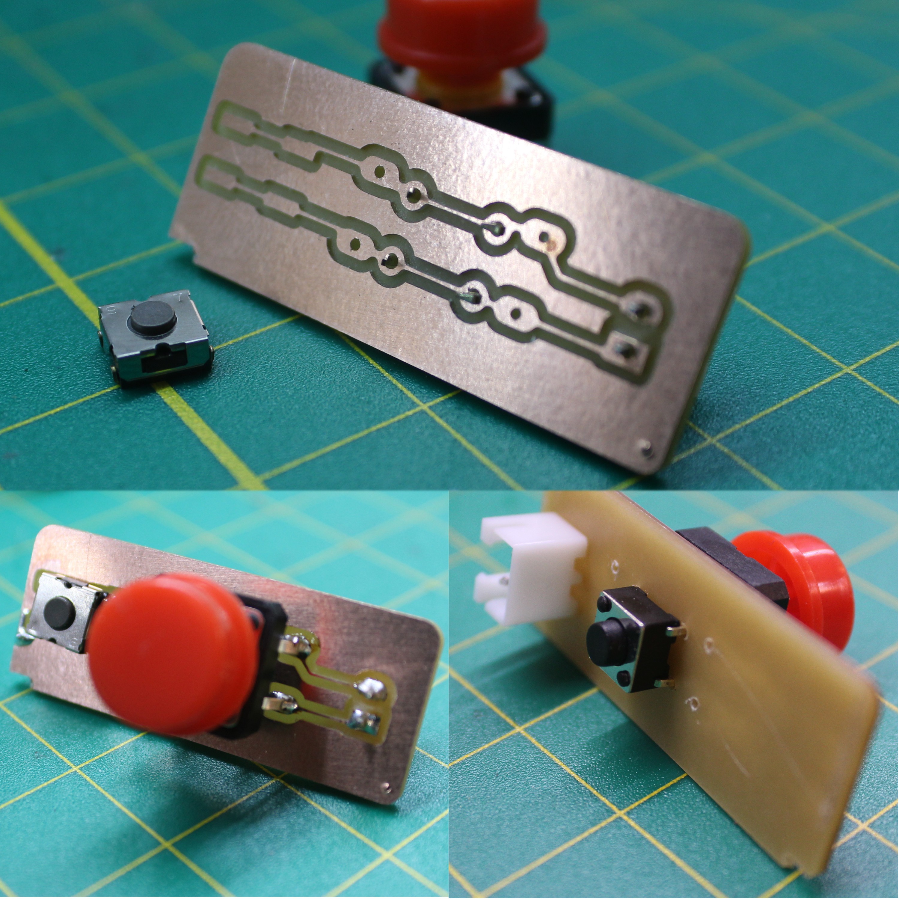
Simple button board that allows fro three type of buttons, and all attached in parallel. But this too is bitter sweet. You see that little divot in the bottom of the board. That's where the board jumped once cut out and broke my third bit for the day. I spoke with Dan on this and explained the measures i went to make sure the surface was cleaned with IPA before covering the entire bottom of the board with double sided stick tape. After the talk we decided to try the other Other Mill. And this is what happened:
Just beautiful. And no issues. Finally things are coming together and I was able to better overlap the buttons for this cut, making the assembly have a smaller footprint still. It's at this point I feel i can finally proceed with some level of understanding and confidence.
All growth outside of comfort will be riddled with failures. but upon these failures we learn the lessons to succeed. On towards the next steps!
~Metal
Discussions
Become a Hackaday.io Member
Create an account to leave a comment. Already have an account? Log In.