 Springuin
I made this in 2011. The idea comes from a friend with a busy job who suggested that after a long day at work answering all those work e-mails it would be nice to have a quick overview of his private e-mail without booting up his computer. I designed this as a non-intrusive solution to get a quick view of new e-mails. The device just sits quietly, connects to a POP or IMAP mailbox, requests the headers of the 10 most recent mails and stores this data. When you want to know if there are any new e-mails you just touch one of the buttons and the display lights up, showing the sender, date and subject of the 10 most recent e-mails in the inbox.
What's nice is that it's completely standalone and you don't need to have it connected to the computer or run a special server or something like that. It just talks POP or IMAP to the server.
It has a USB port to configure it. You connect it to the computer, run the configuration program, enter the WiFi and e-mail details and from that moment on it starts reading e-mails.
Finally made 3 pieces, one for him and two others for family members. The design is more or less made with production in mind but I never continued that because the cost price was too high, the RN131 WiFi module being the most expensive part.
Tools used:
- Firmware written in C with AVR-GCC, using Eclipse as IDE.
- AVR Dragon as programmer/debugger
- PC software to configure the device written in C# using MonoDevelop. The software runs both on Linux and Windows.
- Enclosure designed in Inkscape and lasercut/engraved by Formulor.
- PCB and schematic in KiCad.
The firmware and configuration tool is available under the GPLv2 license.
The bootloader is a slightly modified bootloader from the Sanguino project (diffrerent baud rate, different CPU clock and different uart used). It's licensed under GPLv2 or later.
The touch buttons use software from Atmel used in binary form. See the README file on the Mailnotifier-Firmware repository on GitHub for more details.
The enclosure and schematic/PCB are available under Creative Commons ShareAlike (CC BY-SA 3.0).


 Dan Julio
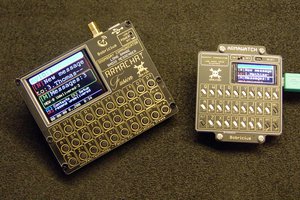
 bobricius
 Platinenmacher
 Casey Banner
I did really enjoy exploring this project. I learned a lot about integrating various libraries and parts.
Thank you..