Close
0%
0%

RGB seven-segment display [RSSD]

My journey to create a big but thin, evenly illuminated seven-segment display.

janJan
Similar projects worth following
There aren't many big(ger than 1") fully-RGB seven-segment displays to choose from on the market. I needed a two-digit version for a clock I am planning to build. So the journey begins...

Goals to reach (updated Nov. 11th, 2018)

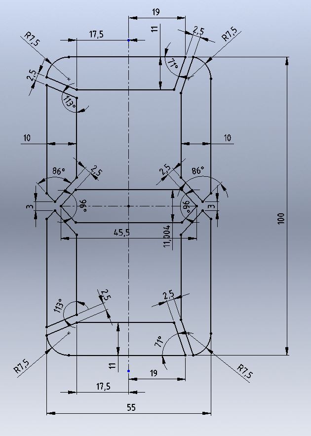
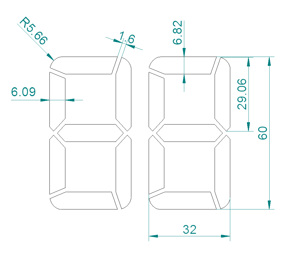
— Number-height of 100mm (approx. 4") @ 10mm thickness

See old post here: https://hackaday.io/project/20142/log/54244-obstacle-1-number-height-of-60mm
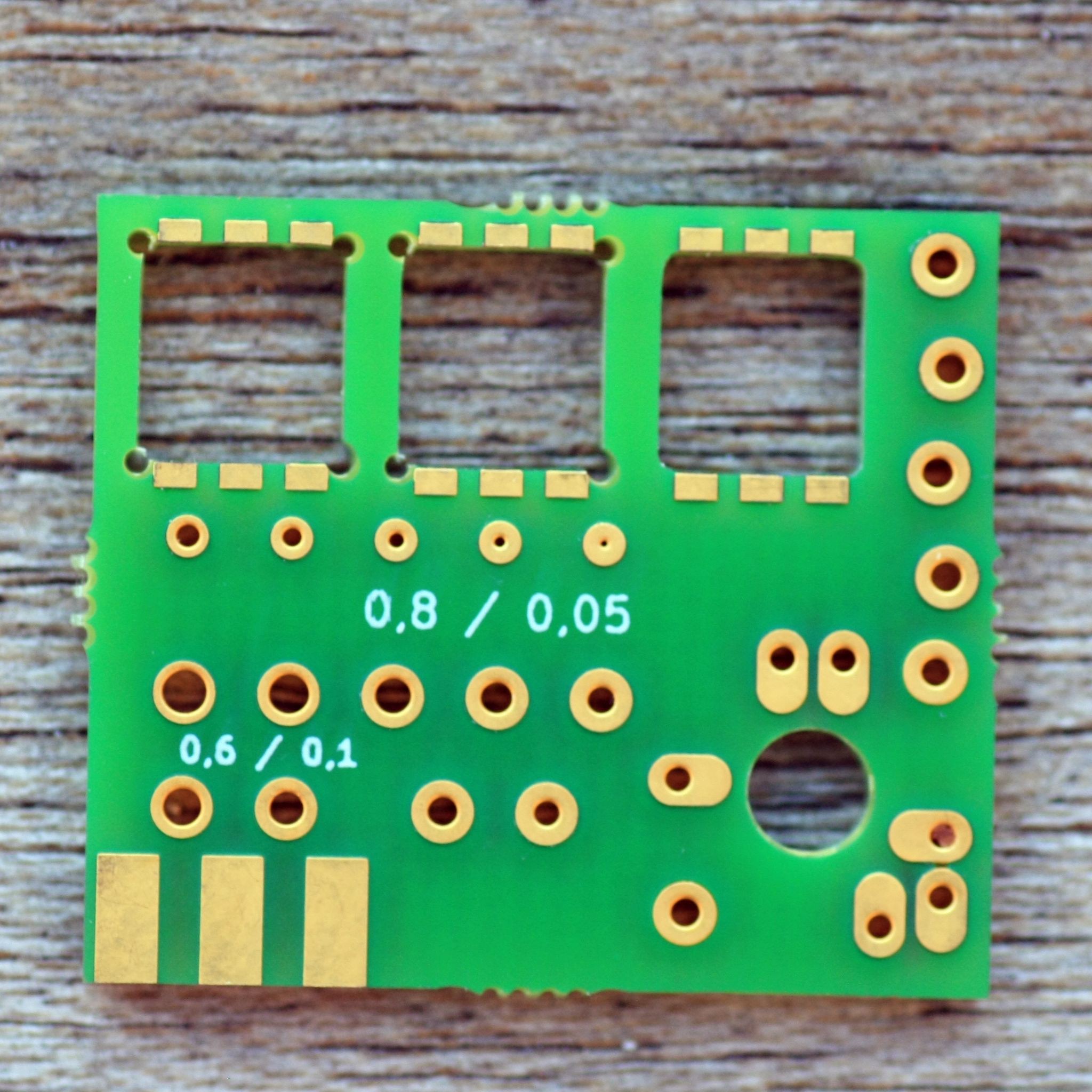
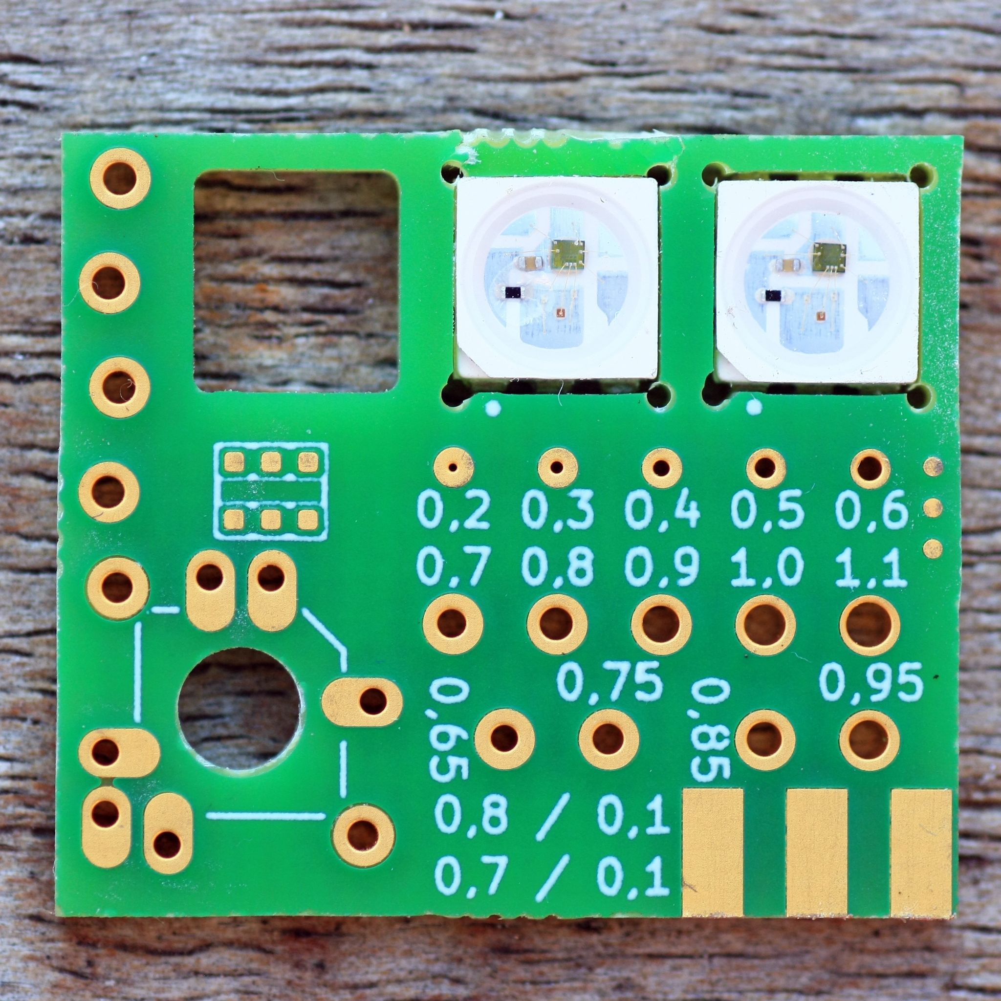
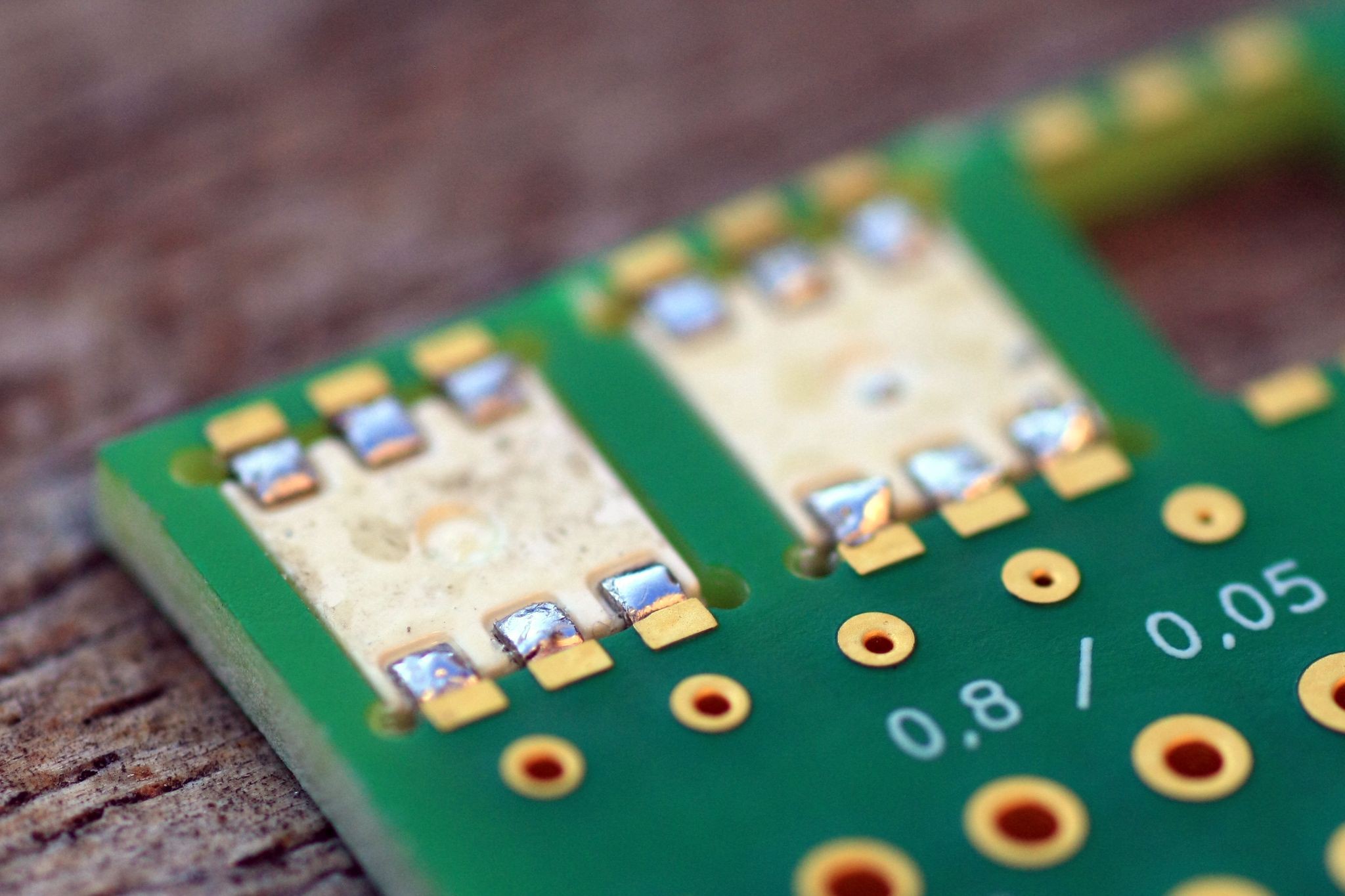
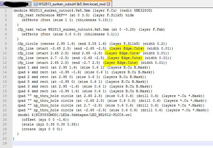
See new post here: https://hackaday.io/project/20142-rgb-seven-segment-display-rssd/log/155852-new-design-includes-special-ws2813-footprint

— Homogeneously illuminated segments

See old post here: Homogeneously illuminated segments

See new post here: to be continued (will be fancy. Promise!)

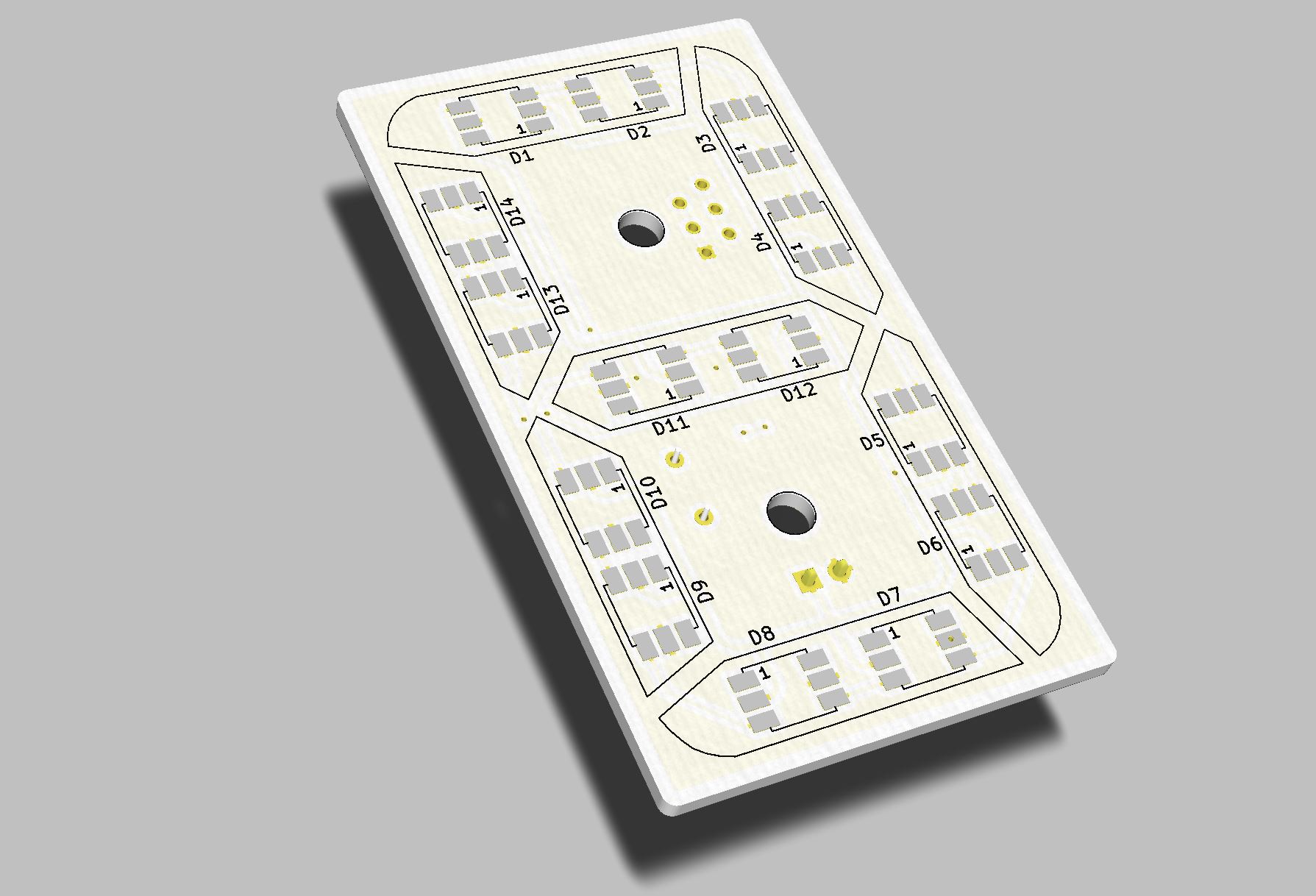
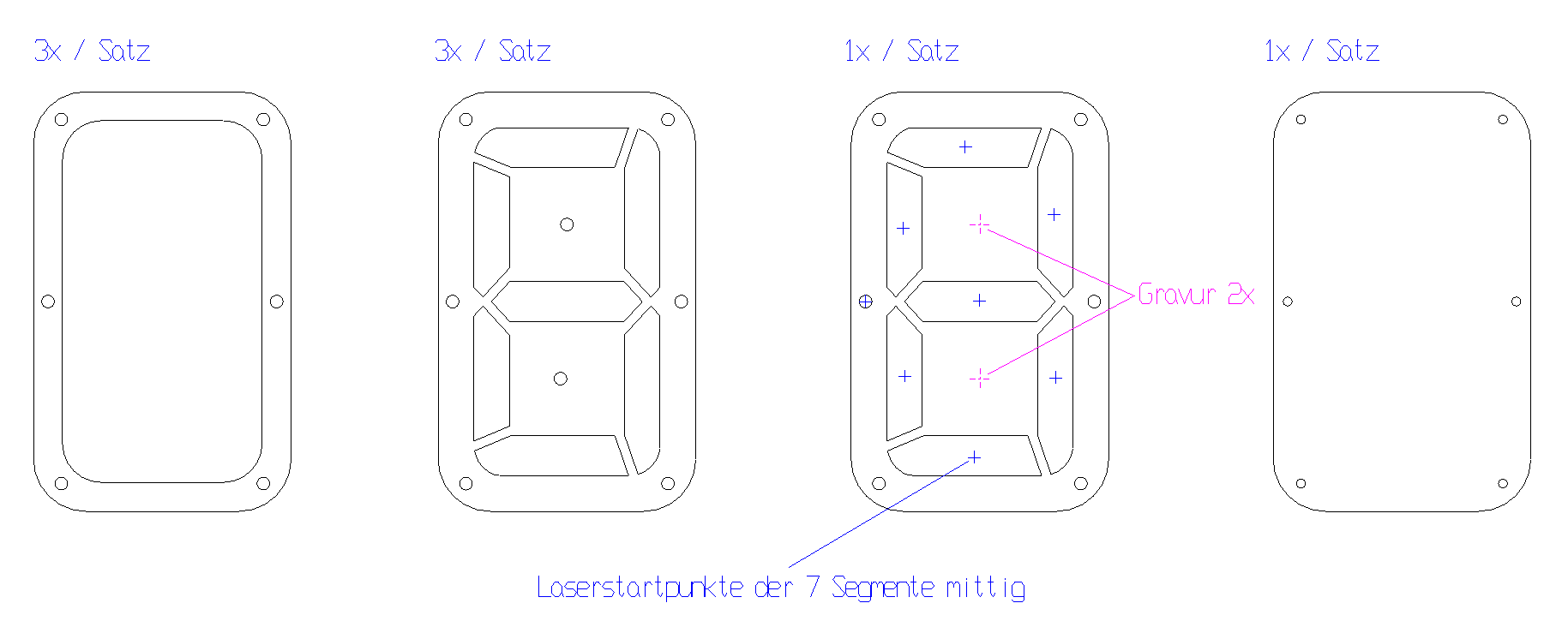
— Clean, unobtrusive design and easy to assemble

  • one PCB per character
  • frame laser-cut wood/steel/whatever you like
  • preferably no screw or hidden screws (magnets?)

See [Blog-Entry]

— More features:

  • programming and power via USB
  • [...]

WS2813_sunken_final_Aisler.kicad_mod

WS2813 footprint with PCB cutout

kicad_mod - 1.37 kB - 11/17/2018 at 14:32

Download

two_colour_test.mp4

Just a small test

MPEG-4 Video - 29.72 MB - 03/23/2017 at 17:08

Download

JPEG Image - 496.56 kB - 03/09/2017 at 15:13

Preview
Download

  • 1 × Set of laser-cutted steel segments
  • 1 × Set of laser-cutted steel plexi glass segments
  • 1 × WS2813 LEDs
  • 1 × misc stuff

  • Power supply considerations

    Jan11/14/2018 at 08:12 0 comments

    A quick primer on powering WS281X LED's

    There's some important things to keep in mind when designing with Worldsemis WS281X LED's. I'll try to keep it short and concise. Here are the main points to consider:

    • type of LED (there's different versions of those LED's available)
    • how many LED's will be on at a time at which color and brightness level
    • what will the power supply be

    We will discuss these in the following paragraphs

    LED types

    Worldsemi (that's what WS stands for) has those LED's in many different styles.

    The famous WS2812 found on LED strips is most likely the WS2812B type, which has a current consumption of 20mA max per color (60mA at full brightness white). They offer some dimmer variants as well, the WS2812C for example. It has only 5mA per color at much less brightness.

    It's the same with the WS2813. There is a 12V variant too, the WS2815B.

    If you're interested in a smaller case, the WS2812C-2020 or the WS2813B-MINI are your choice, which come in a 2020 respectively 3535 case.

    I ordered my LED's at lcsc.com. I guess Aliexpress etc. has them too (wouldn't be surprised if there are fakes out there).

    Active LED's at once

    This is the most important factor for choosing a power supply! You should always consider the worst case scenario of your application.

    In my case this will be the time displayed with most segments on at maximum brightness in white color (*3 because of 3 LEDs per segment):

    Time23:
    58
    LED's lit
    (5 + 5)*32
    (5 + 7)*3
    Current consumpt. [mA]
    1800
    1202160

    This is 4.08A at 5V = 20.4W. At an estimated 85% efficiency of a wall plug this is 23.5W of total mains power usage.

    Another way to ship around this is to use only 1 or 2 LED's per segment. With 2 LED's the current would be 2.76A, with only one LED 1.44A.

    Power supply considerations

    4.08A is too much for the standard USB 1.0 / 2.0 output (500mA max) and even for all those USB-phone chargers which deliver up to 2.1A.

    We also need to take into consideration that when programming the clock, it might only connected be to the PCs USB port (which might even be USB 1.0, who knows). So there needs to be a low-power mode for programming which is preferably activated automatically.

    So, for this clock I will use a 5V, 25W standard power supply. Expecting all segments active would draw 5.4A from the supply which is totally unrealistic...

    Final considerations

    The clock won't run this brightly for any longer period of time, so the above values are very conservative. I expect it to use a maximum of 1.8 - 2A at a "good to read in daylight brightness". But in normal operation it'll draw something around 1A or less.

    The FastLed library has options to restrict power consumption, we'll look into that later on.

  • New design (includes special WS2813 footprint)

    Jan11/12/2018 at 11:56 4 comments

    Font overhaul

    The layout of the segments has been revised. Dimensions are as in the following drawing.

    You can see that everything is now nicely symmetrical, aligned and has even dimensions in mm for all important features (segment width, supports between segments, character height). I did this to have it scale down nicely to 50mm (segment-width is 5mm in that case) and bigger is easily scaled too.

    Optical correction of the corner-segments

    This is something that always annoyed me with this font. The marked corners do no look aligned, though they are perfectly in line. They seem to stick out a bit. This is an optical thing, which needs to be corrected by an offset.


    Here's the version with corrected corners:


    Here's how little correction is needed (0.3mm):

    Foundation of my work is the digital-7 font which is free for personal use. By the way. There even is a Segment Displays Wiki on the net, exclusively dedicated to segmented displays and fonts. Wow :)

    LED's per segment

    For the 100mm font-height 3 LED's per segment are used to achieve the "top-to-bottom rainbow effect" I want to have with the finished 4-character-display (plus separating colon)

    I want to show the time as 24 hour format plus maybe temperature and/or date.

    Modularity

    Many different PCBs for each segment would result in no bulk discount at most PCB manufacturers, so I created one PCB, which can be used for every 7-segment-letter including the colon.

    Later there will be four "dumb" segments with just LED's and one smart segment, which in turn controls the four others.

    Each segment has all LED's in series plus an input and output connector. A solder bridge tells the "smart segment" which one is first and which is last.

    Control of the Segments

    One master-segment has all the parts placed to control further segments. The programming is done via USB (CH330N USB/UART bridge). It uses the same driver as the well known CH340 from all those cheap Arduino clones.

    It has three pots (yes pots, not rotary encoders) to set the time and color of each/all segments. As the clock works in HSV-color mode, there's one pot for each value.

    Reducing the overall height

    This step includes two aspects:

    1. setting the LED's in into the PCB
    2. adding more diffusion because there's less overhead space for the LED's light to mix now

    Setting-in of the LED's

    This is done by creating a slightly undersized cutout of 4.9x5.3mm in the PCB for each LED. This makes soldering much easier. LED's are pressed in by hand with little force. There's no need for further aligning, just solder them from the bottom-side and you're done.

    PCBs are from Aisler this time as they only take 8 days from uploading Gerbers to your mailbox if you live in Germany. I already asked them about their cutout-quality. Edges are not as straight as I am used to by OSHPark...

    PCB - bottom
    WS2813 - they align differently because I used desoldered ones from an RGB LED strip
    bottom side

    You can download the KiCAD footprint here: https://cdn.hackaday.io/files/20142861755328/WS2813_sunken_final_Aisler.kicad_mod

    It is not possible (at least not in KiCAD 5.0.1) to draw lines on the Edge Cuts layer. If you wonder how it's done: draw the cutout on the DWG User layer, save the file, open it in a text editor and substitute your "layer dwgs.User" with "layer Edge.Cuts":

    Save your file and close/reload your KiCAD. Be aware that modifications to these lines in the KiCAD footprint editor will give you errors, telling you it has detected segments on unsupported layers. Just click "Cancel" and you're fine.

  • Update coming shortly

    Jan11/12/2018 at 09:12 0 comments

    Work on this project has been continued! I ordered a test PCB to try something new. Should arrive end of this week, I'll update my log then.

    In a nutshell it'll be about getting everything thinner while making the whole unit bigger. I'll go for 100mm segment height and have worked on the "font" a bit. It's now easily scaled while maintaining enough space for the WS2813 LEDs.

    New goal is to get down to 10mm thickness @ 100mm text height!

    Talking about LEDs: I ordered 150x WS2813Bs and and 50x WS2812B mini (3535 case).

  • Short video and PCB prototype

    Jan03/23/2017 at 17:22 0 comments

    I've been on a short trip, so I had little time for my project. Anyway I've created a prototype PCB (through-hole components will be substituted with SMD parts soon):

    I'll use two LEDs for each segment to keep the overall thickness to less than 15mm. I added a short video in the files section which shows one segment lit with two different colors.

    I think very cool effects will be possible with this configuration. The PCB will get an Atmega328, ISCP etc for programming so the unit can be used on its own.

  • Laser-cutted parts arrived

    Jan03/09/2017 at 15:16 7 comments

    Laser-cutted segments arrived today. They are a bit loose (maybe 0,1mm or so) but they'll fit snuggly when everything is powder-coated/laquered.


    Yay, the laser-cutted steel parts arrived today. They look great:

  • Obstacle 2: Homogeneously illuminated segments

    Jan03/02/2017 at 19:52 0 comments

    Problem

    This is the real problem. I don't want to use more than two LEDs per segment. Segments are somewhere from 25 to 29mm long. Using one LED is not enought to get an even glow. Using two creates a "dark spot" between them...

    Solution

    Lot's of testing had to be done! I ordered a few laser-cutted steel plates (2mm thick) to play with:

    Number one and two (from the left) are spacer plates which I'll use to get some space between the light-source and the front plate. Plate number three is the front plate, where laser-cutted acrylic segments (opaque plexi) will be pressed in. Last one is the back-plate.

  • Obstacle 1: number-height of 60mm

    Jan03/02/2017 at 19:34 0 comments

    Problem

    As I wanted to use spare WS2813 LEDs I have lying around, I needed a typeface which has wide enough segments to fit these at a height of 60mm. A quick google search for "led font" or "7 segment font" gave lots of options to choose from.

    Solution

    My first choice was Open 24 Display st by southype.

    The problem here is the number "1". As the segments don't reach the top/bottom segments number 1 seems much smaller than the other digits. Another search brought up Digital-7 by Style-7.

    Ah, much nicer! After converting it from .ttf to vector I had to modify it slightly to get it to the dimensions I needed. Height is exactly 60mm, width is 32mm. A few of the dimensions:

    Width of the single segments is enough to fit the 5x5mm LEDs. I modified the bridges between the segments to 1,6mm so laser utting from 2mm thick steel won't yield any problems.

View all 7 project logs

Enjoy this project?

Share

Discussions

Xasin wrote 12/06/2018 at 11:34 point

Gha, seems like you got to this project before I did!
I wanted to make a simple four-digit seven segment display countdown for New Years eve, but I'm making it a lot simpler than yours ^^'

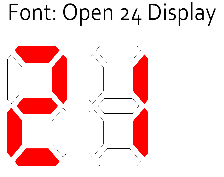
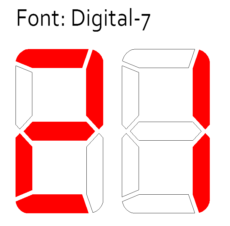
Seems like you're putting a lot of thought into this, which is nice! The font certainly looks nice :D

What will the main controller be? I can highly recommend a ESP WROOM module. Easy to solder, cheap enough, and the ESP32 has a built-in digital signal generator that can control a good number of WS2812 LEDs from hardware.

It's also got WiFi and has the processing power for smooth animations~

  Are you sure? yes | no

Jan wrote 12/06/2018 at 15:26 point

Hi Xasin. Ideas are just that: ideas. So go ahead and build your version. Could easily be finished before my clock :) 

I'll go my usual Atmega way, I don't like IoT everything too much. Maybe! Bluetooth... 

I don't envision too fancy animations, just a few cool, basic effects... 

  Are you sure? yes | no

Xasin wrote 12/06/2018 at 15:29 point

*Chuckles*
Actually, at the time of writing, I am already printing out the first few segments.
One big difference certainly is that yours is made for good looks, which is quite appreciable, while mine's more of a ... Minimalist approach (thin 3D printed pieces, for example)
In return, I get 30cm high pieces that'll be easy to build in time for new year~

Can't wait to see your version though. The font looks fantastic!

  Are you sure? yes | no

Jan wrote 12/07/2018 at 08:05 point

@Xasin

Yeah,I just modified it slightly, credits go to the fonts creator :) 

Will you create a log for your build? I'd be much interested in a few pics! 

  Are you sure? yes | no

Xasin wrote 12/07/2018 at 11:15 point

I'll most certainly do! Haven't gotten around to making the Hackaday project yet, but I'll do that probably during the weekend. There'll be plenty of videos of me trying out different transition effects between numbers. Flashing countdowns and stuff <3

  Are you sure? yes | no

Jan wrote 12/07/2018 at 11:22 point

Nice, I'll get myself a few ideas from you then, right? :)

  Are you sure? yes | no

Xasin wrote 12/15/2018 at 22:24 point

  Are you sure? yes | no

Bharbour wrote 01/28/2018 at 22:58 point

Nice project, did you ever finish your thermometer project?

  Are you sure? yes | no

Jan wrote 01/29/2018 at 18:10 point

Thanks for your comment Bharbour! Unfortunately I shelved that project for other thing I deemed more important :)
The day should have at least 48 hours to get all the stuff done!

  Are you sure? yes | no

Maksim Surguy wrote 03/10/2017 at 20:00 point

Great project! I'm working on a similar project here: https://hackaday.io/project/18760-neosegment-7-segment-display-made-with-neopixels 

  Are you sure? yes | no

Similar Projects

Does this project spark your interest?

Become a member to follow this project and never miss any updates