 DIY GUY Chris
Introduction:
Since a lot of our followers asked for a tutorial to guide them to make a basic Robot we decided to provide this instructable that describe a step by step making of LINE FOLLOWER Robot,so you will find all the necessary software and hardware parts to make your own Robot following these steps
Note: In this project the main part which is the PCB design was made using EasyEDA Platform, so refer to the PCB MAKING section to learn more about this step.
Description:
A Robot is any machine which is completely automatic, it starts on its own, decides its own way of work, stops on its own it is a system that contains sensors, control systems, manipulators, power supplies and software all working together to perform a task automatically with speed and precision. There are as many different types of robots as there are tasks for them to perform.
Any robot has these essential characteristics: Sensing, Movement, Energy and Intelligence.
What Is a Line Follower Robot?
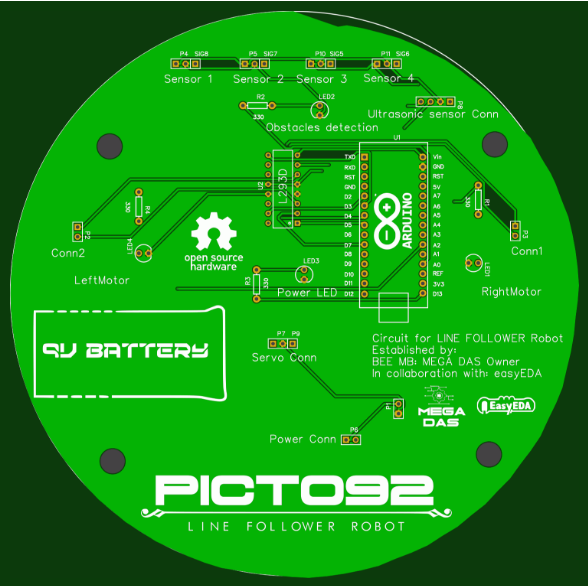
Named line follower robot simply because it follows the black track that you design for it so we need two DC motors to make it move and for sure some sensors like the IR transceiver to detect the line and follow it, without forgetting the processing unit which is an Arduino Nano in our project but you can use other microcontrollers to be able to drive the wheels depending on the sensors
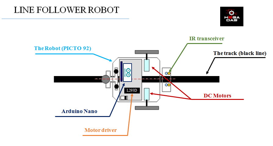
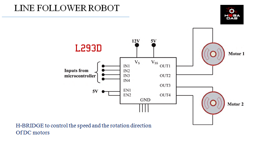
We need an L293 motor driver which allows us to control the direction and the speed of DC motors. So if you want to make the robot turn left you should slow down the left motor and speed up the right motor, the opposed case for turning right and keep both motors running at the same speed for straight movement.
But how to find the black line!
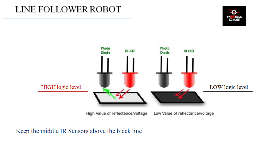
To make the robot follow the line, IR sensors are employed with the fact that black surface absorbs light and white surface reflects light. The sensors are mounted on left front end and right front end of the robot keeping the black line lies in between them until sensors are getting the reflected light, the comparator sends logic 1 to the microcontroller and the microcontroller in turn switches ON the motor associated with the sensor and when any of the sensors comes up on the black line the microcontroller stops the motor associated with that sensors and make the robot turn in the direction of the black line.
When the robot reaches end point and both the sensors are getting black surface, robot stops.
Design of the Mechanism
A Robot should have a structure to hold the electronic parts so we did some software design for the robot I mean the robot mechanism and to do this I used SolidWorks software to make the upper base and the lower base for the robot so you can find and I provided the (.dxf) files if you want to make some CNC laser cutting and produce your own mechanism.
The PCB Design Using EasyEDA Platform
About EasyEDA!
EasyEDA is a free online Electronic design automation community that allows the creation, testing and editing of schematics and PCBs.
Find the link to the easyEDA platform here.
This online program is supported in all platforms even android, with easyEDA you can make a Schematic Capture for your documents, Circuit Simulation, Online PCB Designing with the ability of importing PCB and Schematic files, so from this point we can understand that we can create the PCB in this online designer or just make it with another software and upload a gerber file to easyEDA to place an order.

How to design the PCB and order it!
As usual we need to run the easyEDA platform from here, then start a new project and import the necessary components like Arduino Nano, L293 motor driver the header connectors etc and connect them together to make the circuit showed in the picture, after that just click on convert project to PCB then you will get your PCB design area.
I advise you to click directly the following link the PCB automatically:Direct link for Line follower Robot project
You can also check the PCB before ordering...
Read more »
 CiferTech
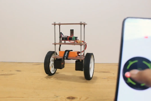
 Mrinnovative