 Lukas Vacek
See info on the bottom of the description.
Floppy disk drive (FDD) basic notes:
Floppy disk is a magnetic medium. The data are stored on magetic disc, which is beeing rotated during the reading process. Speed of the rotation of disk is 5 times per second. There is a magnetic head that reads the transitions of a magnetic flux and they are (somehow) interpreted as logic states.
Floppy medias & capacity calculations:
There are two common 3.5" media of types: "dual density" DD and "high density " HD:
DD: 2 x 80 x 18 x 512 B = 1 474 560 B = 1 440 x 1024 B = 1440 kB = 1.44 MB, (most common)
HD: 2 x 80 x 9 x 512 B = 737 280 B = 720 x 1024 B = 720 kB,
interpretation:
2 sides, 80 concentric tracks, 18 or 9 sectors by 512 bytes. Tracks are numbered 00-79 where Track 00 is the outermost (the "first track"). You can get more familiar with the concept of CHS on javascript calculator http://www.deathwombat.com/diskgeometry.html
physical differences:
DD has only write protect window.
HD has a write protect window and window on the another side that denotes HD property
ED: there exist also 2.88MB extended density floppy with window located somehow above usual position of window on HD medium, but I have never had such floppy in my hands. I consider ED floppies as very rare. Their drawback is (were) price.
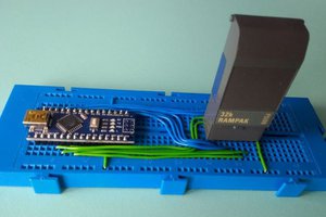
FDD Pinout:
Pinout description can be found at http://pinouts.ru/HD/InternalDisk_pinout.shtml
There is a 5V logic in floppy drive, same as in Arduino UNO. The I/O pins of FDD have internal 2kOhm pull-up resistors. Signals from FDD are short drops to 0V (from +5V to 0V and then again back to +5V). Setting FDD pin to +5V is in fact same as leaving it unconnected since its automatically pulled-up by internal resistor.
Most important pins for reading are outputs READ DATA and INDEX.
INDEX - FDD output pin
gives short drop to 0V every disk revolution on specific position that determines the start of track. (start of all 80 tracks). The drop occures every 200ms (5 times per second).
READ DATA - FDD output pin
HD floppy
READ DATA output pin gives stream of drops with descriped pauses between them: (2,3,4) microseconds called modifiend frequency modulation (MFM). See wiki or floppy PDF manuals attached.
DD floppy
For sake of simplicity here just shortly about easier FM: FM encoding for DD 720k floppies means that log 0 wil be encoded as Rnnn and log 1 will be encoded as RnRn, where Rn means flux transition and nn means no flux transition. So 1 is encoded as two flux transitions wheras 0 is encoded as one flux transition = two drops vs. one drop. There is nice example on wiki, see "MFM encoding".
Other FDD input pins:
for distiguishing floppy drive A: and B: on same ribbon cable
for enabling appropriate motor A or B
denote that there is a special mechnism of cable twist on FDD ribbon cable that allows to switch between A and B withouth jumpering them. google for details "FDD cable twist".
for enabling writing data (settting low means writing enable)
for writing data (stream of pulses that represents flux transitions to be written)
for side select (the one or the another)
for direction of a servo (inwards/outwards)
for step of R/W head by one track in direction specified (... specified one line latter)
other: (not needed for us)
Half of all the pins are grounded. Whole one line of pins in FDD connector can be wired together.
--------------------
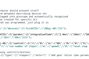
Essential knowledge point: digitalRead(.) is too slow for our purposes. Same holds for digiralWrite probably, but it is not needed for us. Use rather direct AVR PORT manipulation commands.
--------------------
Note: PDFs of floppy disk drives specifications I found on internet are for different floppy drives but since we expect most of standard floppy drives can work on all computers there could be hardly large differences between them. I am providing you few datasheets attached...
Read more »
 martin
 Gintaras Valatka
how many more GPIO pins and code space is needed to add a SCSI interface for this floppy controller?